


With Intent to Improve.
Page 24
If you've noticed an error in this article please click here to report it so we can fix it.
A Weekly Summary of Recent Patents, of Interest to the Maker and User of Commercial Motor Vehicles.
Selected and Abridged by H. S. Hall, A.M.I.A.E.
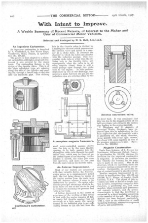
An Ingenious Carburetter.
An ingenious carburetter is described by A. Couffinhall, 6, Rue Victor Hugo, Vourbevoie, Seine, France, in specification No. 104,221.
The patent is best adapted to a threejet carburetter, although a.single-jet component is also covered by the claims made. The outstanding feature is the design of the throttle valve. This is of the plain cylindrical type, air entering along-the axis of the cylinder and passing out through a bored hole at the side into the induction pipe. This delivery, hole in the throttle valve is divided by a rectangular channel which passes across the throttle valve and serves in a manner as a choke tube. It connects the chamber in which the tubes are situated with the induction passage. This rectangular choke tube is wider than the delivery hole in the throttle., valve, and consequently when the valve is in all other respects closed, there is still a small passage open through this choke
tube to the engine. In this position, illustrated by one of our drawings, connection is made between one jet and the induction pipe, air entering either by the small screw-controlled passage shown near the jets, or by the main throttle opening, or by both, passing into the rectangular choke tube through the small drilled hole, which may be observed on the central figure of our drawing. As the throttle is opened, the other . jets come into operation, and more air can pass from the main hole in the throttle valve.
An Autovac Improvement.
.Most of our readers are acquainted with that valuable device, the Autovac, which serves as a supplementary petrol tank, the fuel being drawn by means of the engine suction from the main tank into the Autovac whence it runs to the carburetter by gravity. On motor vehicles the principal advantage which is derived from the use of this device is that obviates the necesSity for pressure feed with a rear tank.
A failing discovered in the course of experience of the working of this device is that with the engine running at full, or nearly lull throttle opening, but not revolving at a high speed, the vacuum formed in the induction pipe is not sufficiently intense to lift the fuel from the low-level tank. It was considered that this was due to the. sluggish action of the ball non-return valve fitted in the suction pipe leading to the engine manifold.
J. Higginson and H. Arundel, of Sovereign Works, Stockport, have improved upon this by substituting for the, hall a light thin disc, the inertia of which is practically nil, and which, therefore, opens quickly with 'every light vacuum, but closes with equal rapidity as soon as the pressure coimirences to rise. (Specification No. 104,256.) Magneto Construction.
Emile Jean Salmson, of 9, Avenue des Moulineaux, Billancourt (Seine), France., in specification No. 104,239, discloses hfs invention for the improved construction of magnetos. It describes the construction whereby the framing for the mag,. neto is made in one piece. One of the drawings, which we reproduce, shows the one-piece casting as suggested by this invention. Incidentally, an accessible design of contact breaker is also illustrated. Another magneto improvement is de-. scribed in specifications Nos. 100,173 and 103,300, by C. Mason, of Sumter, South Carolina, tJ.S.A. The object of this invention has been to devise a simple igni'lion dynamo, comprising a magnetic field structure, a generating coil, and rotor member, whose members have permanent and opposite polarity, and its special characteristicis that the distributor is connected by a short insulated connection to the terminal of the coil. This ignition dynamo has been designed particularly with a view to the elimination of small insulating bushings, compact arrangement of parts, and accessibility.