


Patents Completed.
Page 30
If you've noticed an error in this article please click here to report it so we can fix it.
Clayton and Shuttleworth Boiler Mounting. IATolseley Differential. Frictiondrive Change-speed Gear. Clarkson Cast-steel Wheel.
Copies of complete specifications of the patents published on this pare can be obtained from the Sales Branch, Patent Office, Holborn, WC., at the cost of sixpence for each specification.
CLAYTON AND •SuuTTLEWORTE, LTD., P. W. ROBSON and F. J. BRETHERTON, No. 16,461, dated 22nd November, 1915.— The principal object of this invention is the provision of an improved connection beta eon the fire-box end of the boiler and the frame of a steam-wagon. The accompanying drawing shows an improved method of mounting a locomotive-type boiler in a chassis. The back plates of the boiler are set back near the footplate and threaded on to a transverse shaft or beam which is mounted on the frame members of the chassis. This shaft may be used as a stationary spindle for some of the transmission gearing of the vehicle. Instead of extending the back plates. of the boiler themselves, extensions may be riveted on to them. The cross-shaft is carried well above the level of the foot, plate, and it therefore leaves the latter very clear, providing ample space for the driver.
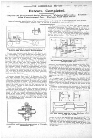
WOLSELEY MOTORS, LTD. and E. J. LERDIt4G, No. 7557, dated 20th November, 191K—This specification describes an improved construction of differential gear of the type in which a frictional resistance is introduced to prevent one road wheel racing when the other is locked. The pinions on the ends of the driving shafts are mounted on sleeves, and a multiple disc brake is provided between them and the cage carrying the planet pinions. One set ef discs is held in the cage and the other set on •the sleeve.
When one of the road wheels offers a greater resistance to turning than does the other, a portion or even the whole of the drive is consequential upon the frictitoial resistance of the clutch. In this way a certain minimum driving effort is transmitted to the locked wheel, such minimum depending upon the frictional resistance. The accompanying drawing shows the arrangement in a spiral spur-wheel type of differential, and the specification also illustrates it as applied to the ordinary bevel differential.
F. HENRIOD-SCHwEIZER, NO. It)472, 1915, dated under International Convention, 4th May, 1914.—This specification describes a friction-drive change-speed gear of the type in which a driving wheel is engaged at various positions with,-.a stepped cone pulley for giving the various speeds. • The special feature of the invention consists in the mechanism for imparting the necessary radial and axial movement
to the driving pulley. The change-speed lever operates, through a rack and pinion, a roller shown in the plan drawing towards the upper right-hand corner. This roller has two cam-slots in it, of which one operates a. bell-crank to provide axial movement and the other operates a lever and swinging link to provide the radial movement of the driving pulley. A. counter-pressure pulley is engaged with the cone to take up the thrust, and the reverse drive is taken through this pulley. The cone gives three speeds and a direct drive by engaging a dog-clutch on the driving pulley with the driven shaft.
T. CLARKSON AND W. J. MORISON' No. 100,376, dated 11th February, 1916.—Cast-steel wheels for motor vehicles areusually made with hollow spokes, but these are disadvantageous in that theNscore for the spokes does not always remain *central, so that the thickness of metal in the spokes is not uniform:
According to this invention the spokes are of II-section and are joined to the rim by webs extending from the limbs of the II and also from the rounded, part of it. The hub, spokes and
rim are all east in one, and this rim may be arranged to take the tire directly or to receive the tire-carrying rim. The extra rim would then be secured in any convenient manner. Sometimes the hub and spokes are east in one, and the outer ends of the spokes are provided with flanges so that a rim' can be shrunk on or welded or riveted to the flanges, to build up the wheel_