


A NEW CHASSIS FOR 20-25 SEATER COACHES.
Page 19
Page 20
If you've noticed an error in this article please click here to report it so we can fix it.
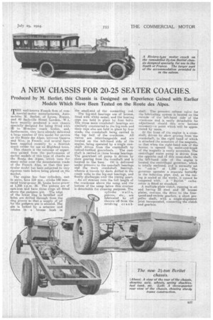
Produced by M. Bei-liet; this Chassis is Designed on Experience Gained with Earlier Models Which Have Been Tested on the Route des Alpes.
MHE well-known French firm of coin
mercial-motor manufacturers, Automobiles N. Berliet, of Lyons, rance, and 40 Sackville Street London, W.1, have recently produced a new chassis specially designed for being fitted with 20 to 25-seater coach bodies, and, furthermore, they have already delivered a large number of this model for service on the Route des Alpes, between Geneva and Nice, in France; and several have been supplied recently to a Scottish coach owner for use on Highland tours.
This chassis is the outcome of experience gained from the performance of earlier models of this type of chassis on the Route des Alpes, which runs for manv miles over the mountainous roads of the French Alps, so that. this particular model has been subjected to very rigorous tests before being placed on the market.
The engine has four cylinders, cast in pairs, bore 110 mm., stroke 140 ram., rated horse-power 30, brake horse-power at 1,350 r.p.m. M. The pistons are of cast-iron and have three rings all fitted above the gudgeon pin. The edge of the lower ring is bevelled and holes are. drilled through from the ring groove so that a• supply of oil for the gudgeon pin is assured. The pin is locked by a setscrew and rotates in a bronze bush in the small-end of the connecting rod.
The big-end bearings are of bronze, lined with white metal, and the bearing caps are held in place by four bolts. The three main crank-shaft bearings are similarly constructed to the big-ends and their caps also are held in place by four studs, the crankshaft being carried in the top half of the crankcase. All valves are interchangeable and are located on the left-band side of the engine, being operated by a single camshaft driven from the crankshaft by
helical-toothed gearwheels. The camshaft is carried in three bronze bearings. The gearwheel oil pump is driven by skew gearing from the camshaft and is
located in the base. Oil is delivered under pressure to the camshaft bearings and the main crankshaft bearings, whence it travels by ducts drilled in the crank webs to the big-end bearings, and finally discharges over the timing gears.
An oil strainer runs the full length of the crankcase above the sump and the bottom of the sump below this strainer is detachable for cleaning purposes. The
cylinder • wall s, pistons, etc., are lubricated by oil thrown off from the revolving crank.
shaft. The pressure release valve for the lubricating system is located on the outside of the left-hand side of the crankcase and is easily detachable for adjustment should this ever become necessary—a point which will be appreciated by users.
At the front of the engine is a crossshaft, driven by skew gearing from the crankshaft, to the right hand of which is attached the armature of the magneto, so that when the right-hand side of the bonnet is opened the make-and-break of the magneto is easily accessible. The centrifugal water pump is driven from the opposite end of this cross-shaft. On the left-hand side of the engine is located the centrifugal governor, which is totally enclosed, and is normally set to " cut-in " at 1,350 r.p.m. The governor operates a separate butterfly in the induction pipe, and, as the casing is sealed at the works, it cannot be tampered with. A " Berliet " carburetter is fitted as standard.
• A multiple plate clutch, running in oil and having 22 steel and 22 bronze plates, conveys the drive to the fourspeed-and-reverse gearbox, a short propeller shaft, with a single-alignment joint incorporated, connecting the clutch and gearbox.
The gearbox is of the selective sliding type with the laysh aft located alongside the mainshaft, both shafts running on substantial ball bearings. The changespeed lever and selector mechanism are contained inside of the gearbox casing, the lever being centrally positioned in the chassis. The gear ratios are as follow i—First speed and reverse, 31.67 to 1; second speed, 18.58 to 1; third speed, 10.77 to 1; fourth speed (direct drive), 6.45 to 1. On tap gear at 1,350 r.p.m. a road speed of approximately 30 m.p.h. can be attained.
Mounted at the rear of the gearbox on an extension of the second-motion shaft is the foot-brake drum, the shoes of which are internal expanding, whilst in the centre of the shoes, and protected by a dustproof and oiltight cover, is a star-type •universal joint. In passing, it would be as well to mention that, a lubricator for this universal joint is fitted on the engine side of the dash and connected to the joint by a -pipe, thus ensuring that lubrication of this very important component is not neglected through its being difficult of access.
The propeller shaft is totally enclosed in a substantial torque tube, at the• forward end of which is a ball bearing, the lubricator. for , which . is also positioned on the dash and connected. thereto in the same. manner as the lubricator for the universal joint.
The rear axle is of the douhle,reduction bevel and spur type, and is semi floating. The first reduction is by bevel gearing and the second reduction by straight-tooth spur pinions, whilst the differential is of the bevel-pinion type. Ample means for adjusting the mesh of the bevel and pinion drive are pro. vided, the axle casing being, split horizontally to enable the dismantling of the final drive to be carried out with ease. The rear wheels are fitted on to -a taper at the ends of the driving shafts, .having two Woodruff keys therein, and are secured by a nut and split-pin. The hand-brake drums are mounted on the rear hubs, and the brake shoes themselves are internal-expanding and fitted with renewable liners.
The front axle is an 1-beam drop forging, with jaw-ended stub axles. '1 no front-wheel hubs are mounted on ball bearings. The tie rod for the steering is placed behind the front axle.
The steering is of the Worm and complete wheel type, and the pillar is comfortably raked.
The chassis frame is constructed from channel section . pressed steel, with five cross-members, a separate threepoint suspended subframe being embodied to carry the engine, which is attached to this sub-frame at four points.
The principal chassis dimensions are as follow :—Overall length, 20 ft. 8 ins. ; overall width, 6 ft. 4.1 ins. ; wheelbase, 12 ft, 11 ins.; track, 5 ft. 7iris. -; dash to end of frame 16 ft. 2i ins. The chassis weight is approximately twe tons.
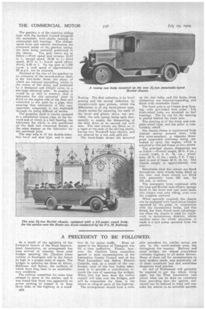
Detachable steel disc wheels are fitted throughout, twin wheela being fitted at the rear, and these wheels are 'fitted with pneumatic tyres 955 mm. by 155 mm. in section.
The pneumatic tyres combined with the long and flexible semi-elliptic springs fitted to the front and rear axles make this chassis very easy riding, even over the roughest surfaces.
. When specially required, the chassis can be equipped with front-wheel brakes operated by the pedal in conjunction with the transmission brake, and this fitting has been found most advantageous when the chassis is used for coachwork in mountainous districts, whilst another extra for which provision is made is a tyre pump operated from the gearbox.