


AN ENGINE FOR HEAVY FUELS.
Page 30
If you've noticed an error in this article please click here to report it so we can fix it.
A Résumé of Recently Published Patents.
AN-interesting . type of _ engine, designed to be capable of working on "-bunker" oils, such 'as are usually burned _under steam boilers, has been invented by W. M. Huskinson, and is patented in specification No. 212,594. ln his design he has kept in view two essentials J-4) That the maximum volume of combustible charge is enclosed in a space presenting the minimum surface of retaining wall; and (2) that the condition of turbulen-ce, existing in the combustible mixture at the time of ignition should be a maximum. In the latter connection the inventor states that. "it is recognized that, where turbulence exists in a combustion chamber, it, is possible to ignite and completely burn a spray of liquid fuel at ,much lower compressions than obtain in the ordinary Diesel engine."
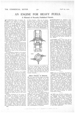
The engine is of the opposed-piston type, in which the pistons compress the gases between them as they approach one another, and are driven apart by the pressure generated as the result of the eXplosion. Tho general construction of the engine will be best understood if reference be made to the accompanying illu.stration.
:The combustion chamber is the narrow connection between the two cylinders. IC is Made , as a separate casting or breech, especially designed to withstand the high temperatures to which it will naturally be subjected. Its walls, as well as the ends of the pistons, which, with it, circumscribe the combustion chamber, are particularly thick so that, they will be able to store up an unusually large proportion of the heat liberated during combustion, and will restore it to the charge of air during compression, thus giving the charge more heat than it receives from the operation of compression only, and facilitating combustion of the fuel when it is sprayed into the chamber.
The fuel jet is located in the middle of the wall of the combustion chamber. The exhaust ports are cut, as may be seen, in the wall of the lower cylinder, so that they. are uncovered by the descending piston as it nears the end of its stroke. The air inlet valves are two in number; they .are disposed pear the base of the upper cylinder, and the entering gases are directed into the cylinder tangentially, and have a slight upWard tendency. The effect, according to the inventor, is to cause them to follow the asc.endirigaupper piston in the form of a large spiral, sweeping the walls of the cylinder, and subsequently descending again as an inner spiral, thus effectively scavenging the. cylinder's and driving the burnt gases out through the exhaust ports in the lower Cylinder.
Extreme turbulence of the gases at the moment' of .ignition is ensured as the result of the peculiar shapeaof the pistons. Each cylinder, it may be noted, tapers sharply to its junction with the combustion chamber. The pistons are of corresponding form, and are. produced, by means of cylindrical extensions, so that they enter the combustion chamber. Their ends are concave, thus contributing towards the efficiency
B46 of that chamber. There is, of course, clearance space between the tapering cods of the piston and the corresponding parts of the cylinders, when the former are at the ends of their strokes. There is also clearance between the cylindrical ends of the pistons and the interior of the breech. Consequently, as
the -pistons approach one another, the gases are, at the end of the stroke, impelled into the cylinder at very high velocity as they are sent out through the narrow space between the ends of the cylinder and the walls of the centbustion chamber.
Other Patents of Interest.
IN the engine patent taken out under specification No. 190,173, by E. H. M. E. Durand, the object is the same as that described in the principal patent we dealt with last week—namely, to ensure that the weight of charge taken into the cylinder during each stroke remains practically constant, notwithstanding the fact that the power unit itself, as when fitted to an aeroplane or airship, may be passing through space in which the density, of the atmosphere is . considerably reduced as compared withthat on the ground level. ' •
The space below the engine piston is made use of as •a compressor, being equipped with automatic inlet and outlet: valves. This compressor operates to fill a receiver, and then automatic
ally ceases to work. Compressed gas from the receiver is only admitted to the engine at the discretion of the pilot, and when he reaches heights where the rarefication of the atmosphere makes it needful. When the pressure in the receiver drops, the compressor automatically recommences to function.
APECIFICATION No. 194,316 is con--`cerned with an improvement to a construction already patented by a certain inventor, G. H. E. de Ram, to which reference has already been made in these. columns. It is in connection with hydraulic suspension systems of the type in which spring-regulated pistons, working in borisontal hydraulic cylinders fixed to the frame of the chassis, are, connected to the axle through a series
of links and levers. In the present patent provision is made, by varying the inclination in the horizontal plane of the main coupling rods to the chassis, for improving the lateral stability of the vehicle.
ANOTHER design which also has as its principal object the increase Of lateral stability is described in specification No. 200,069, 'by L. F. Rousseau. He claims for the mechanism which lie has invented that it acts also as a shock absorber. The design embodies two pairs of floating levers. Of one pair, One lever, transverse and horizontal, is pivoted on the chassis on its longitudi
nal axis. One end of this lever is coupled to a piston, which worksvertically in a cylinder and is spring-controlled ; its other end is ball-jointed, and serves as a fulcrum for the other lever of this pair, the second lever being L-shaped, with its fulcrum in the anglea
of the L. The vertical arm of this lever is short, and is coupled to a spring controlled piston in a horizontal dash pot ; the horizontal arm is long, and is coupled by a' floating connection to the
rear axle. As the axle and frame tend
to approach or recede,, ono to and from the other, the springs in the dashpots operate, supplementingthe action of the ordinary semi-elliptic springs on which the chassis is mounted, and prevent excessive side-sway..
THE form of suspension described 'in specification No. 212,590, by ds Chandler, embodies combined helical and laminated springs. A serai-elliptic spring, having one or more compare; tively thin and flexible leaves, is attached to the chassis in the ordinary
way. The helical springs, of which there may be one or more pairs to each axle are supported between cup-shaped brackets on axle and frame. In some cases, in order to ensure that longitudinalshacks are. net transmitted to these helical springs,. the laminated, spring is permitted to Slide in the lower bracket. A sprung radius rod is -fitted below each sat of springs to absorb longitudinal shocks.
A NEW type of motor plough is de scribed by H. Malhay, in specification No. 194,699. The coulter, instead of being either a plain knife or a simple disc, is a rotating tool with several cutters mounted upon it. 'It is designed positively to 1;yeen up the ground ahead of the plough-share, and its depth of cut, relative to the depth of penetration of the plough, is adjustable, thus making a sery useful appliance.