 1
1 2
2 3
3 4
4 5
5 6
6 7
7 8
8 9
9 10
10 11
11 12
12 13
13 14
14 15
15 16
16 17
17 18
18 19
19 20
20 21
21 22
22 23
23 24
24 25
25 26
26 27
27 28
28 29
29 30
30 31
31 32
32 33
33 34
34 35
35 36
36 37
37 38
38 39
39 40
40 41
41 42
42 43
43 44
44 45
45 46
46 47
47 48
48 49
49 50
50 51
51 52
52 53
53 54
54 55
55 56
56 57
57 58
58 59
59 60
60 61
61 62
62 63
63 64
64 65
65 66
66 67
67 68
68 69
69 70
70 71
71 72
72 73
73 74
74 75
75 76
76 77
77 78
78 79
79 80
80 81
81 82
82 83
83 84
84 85
85 86
86 87
87 88
88 89
89 90
90 91
91 92
92 93
93 94
94 95
95 96
96 97
97 98
98 99
99 100
100 101
101 102
102 103
103 104
104 105
105 106
106 107
107 108
108 109
109 110
110 111
111 112
112 113
113 114
114 115
115 116
116 117
117 118
118 119
119 120
120 121
121 122
122 123
123 124
124 125
125 126
126 127
127 128
128 129
129 130
130 131
131 132
132 133
133 134
134 135
135 136
136 137
137 138
138 139
139 140
140 141
141 142
142 143
143 144
144 145
145 146
146 147
147 148
148 149
149 150
150 151
151 152
152 153
153 154
154 155
155 156
156 157
157 158
158 159
159 160
160 161
161 162
162 163
163 164
164 165
165 166
166 167
167 168
168 169
169 170
170 171
171 172
172 173
173 174
174 175
175 176
176 177
177 178
178 179
179 180
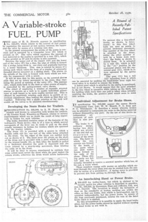
180 A Variable-stroke FUEL PUMP
Page 126
If you've noticed an error in this article please click here to report it so we can fix it.
THE name of H. It. Ricardo appears in specification No. 835,270, which relates to the control of fuel pumps by regulating the amount of lost motion between the tappet and the valve by means of a rotating cam disc.
In the present arrangement the stroke of the pump is con?taut and Is operated by a triangular lever (D) which is pivoted on DI. The valve which regulates tho amount of fuel delivered to the engine is operated by a cam (Hi), which is also pivoted on Di and its stroke is also constant.
Between the upper end of the tappet (G3) and the lower end of the valve (F) lies a disc, the edge of which is formed like a wedge, being thick in one place and gradually tapering to a lesser thickness. This cam is rotated by means of a sliding rack which takes the form of a number of externally threaded sleeves mounted on a sliding shaft.. The pinion on the spindle of the cam is formed with teeth which are suitable for engagement with a screw.
It will be seen that by this means, as the screwed sleeves slide they .set up rotary movement in the cams, thus regulating the period of opening of the valve (F). The Passage (El), which leads back to the tank or other source of supply, Is controlled by the spring-pressed valve shown.
The object of employing a number of separate screwed sleeves to operate as a rack is to enable individual adjustment of each tappet to be more readily carried out. This is effected by separately rotating each sleeve to permit of individual adjustment, then locking the whole so that they act together. Following this a slight rotation of the rack will enable all the valves to be adjusted simultaneously.
Developing the Neate Brake for Trailers.
SPECIFICATION No. 335,300, by R. W. Neate, who is already well known in connection with brakes for trailers, of 62, London Road, Kingston-on-Thames, relates to certain improvements which are no doubt the result of long experience in brakes for such vehicles.
The brake described contains many of the features of the well-known Neate device; this is of a type in which several movements of the lever can be made to pull up the slack usually necessary in brakes for trailers which are operated from the tractor vehicle.
The drum (1) is provided with a groove in which a flexible cable can lie ; one end of the cable being attached to the drum. On the edges of the drum are ratchet teeth cut as shown at 2. The hand lever (6) pivots on the shaft of the drum and is provided with a pawl which is actuated by the jointed handle (5), so that.when the handle is pulled in a backward direction the pawl is depressed and the drum rotated by a step-by-step movement, thus winding the cable on to the drum.
It will be clear to anyone experienced in ratchets that some 6.-etent must arrest the drum while the pawl makes the return stroke, otherwise the drum would rotate backwards. To prevent this a free-wheel device, as shown, is introduced; in this free wheel balls are used as pawls to prevent backward movement. One member of the free wheel is attached to the dram, whilst the other member is held by a brake from rotation; the brake is shown in dotted lines. It is actuated by a cam (9), which is held in the " on" position by the segmental pinion and the segmental gear (11), which is in turn operated by the spring shown. ,
The gear. (11) has a tail (12) extending from it which can be operated by pushing the hand-brake lever right forward when it is desired to release the brake..
A detent pawl which is attached to the casing is mentioned, but is not shown. It would appear that the pawl attached to the free wheel is operative while taking up the slack, but for holding while more than one pull is taken when actually applying the brake, the positive pawl would seem to come into action.
Individual Adjustment for Brake Shoes.
IN specification No. 335,260 appear the names Morris
Commercial Cars, Ltd., W. W. Hamill, P. G. Rose and F. C. Whitehouse. It describes a means whereby brakes can be adjusted to compensate for wear in the facing material -without dismantling any part. By the use of this device an independent adjustment of each shoe is also possible.
The brake is of ordinary design, having two shoes which are pivoted at one end and are separated by means of the usual cam. The faces on which the cam onerate are formed by the heads of two parts which can slide within bosses formed on the ends of the shoes. These slid
ing parts are hol
355,260
low and are internally threaded to receive its end, a worm wheel.
a screwed member which has, at These members engage with worms on spindles which extend through the cover plate and can be rotated from the outside by means of a screwdriver. A spring cover is provided to prevent dirt from getting in.through the hole.
An Interlocking. Hand or Power Brake.
A BRAKE for trolley-buses, but which is claimed to be equally useful for other vehicles is described in specification No. 335,338, by Ransomes, Sims and Jefferies, Ltd., and F. A. Garrett. The invention is simply the formation of dogs on the camshafts of brakes, workinob one within the other, so that one brake, that which is hand-applied, can be operated independently, but the power brake, by means of the clogs previously mentioned, rotates the cam of the hand brake when it is applied.
By this arrangement it is possible to apply the hand brake alone but the power brake cannot be applied without causing the hand brake to act with it.