


Hubs and mechanical brake gear
Page 61
Page 62
If you've noticed an error in this article please click here to report it so we can fix it.
Cleanliness and correct adjustment are the keys to high trouble-free mileages LAST WEEK I covered the overhaul of a Rubery Owen R type suspension to the point of fitting new springs. This week I continue with overhauling the hubs and the brake units to the point where they connect to the air chambers.
Stripping a hub presents no problems in a well-equipped garage. Only under reasonably clean conditions, however, can the completed overhaul be a certain success.
As with the suspension overhaul last week, only normal hand tools and the minimum amount of special tools were used in this exercise.
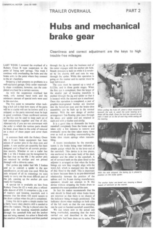
The first point to remember when tackling a hub job is that how many of the parts will be re-usable will not be known until it is stripped, so the parts removed must be kept in good condition. Clean cardboard cartons or the like can be used to keep each set of hub components together and free of dirt. Alternatively if you are not conversant with the order in which the various parts should be fitted, place them in the order of removal on a sheet of clean paper and cover them over.
A common fault with the Rubery Owen Mk 1 S-cam brake equipment has been seizure of anchor pins in the shoe eyes and spider. A new anchor pin assembly has been designed and is fitted on all current production models. Whether or not a trailer has Mk 1 or Mk 2 brakes can be recognized by the fact that on the Mk 2 the anchor pins are retained by circlips and not pinned through with a drive-in cotter.
Our guinea pig trailer had Mk 2 brakes and so to convert a spider to the new specification, an old axle was used. With the axle stripped of all its trimmings we were ready to carry out the most difficult part of the job, opening up the anchor pin eyes ready for bushing.
A special kit is available on hire from Rubery Owen for £2 a week plus a refundable deposit of £50. It comprises a jig, a set of reamers and locating mandrels and it ensures that the shoes will stand square to the drum surface when the job is completed. Using this kit is quite a simple matter but fairly heavy duty electric drill is needed to rive the reamers. The jig is placed onto the pider with the locating mandrels pushed hrough the camshaft hole and the anchor ye not being reamed. An arbor is fitted with e smallest of three reamers and then pushed through the jig so that the business end of the cutter engages with the anchor pin hole.
Steady pressure is held on while it is revolved by the electric drill and cuts its way through the spider. While this operation is going on the reamer and its carrier must be kept lubricated.
The eyes must be opened up a total of 0.125in. and in three gentle stages. When the first eye is completed, then the larger of the smaller pair of locating mandrels is pushed through the jig and spider so that it is located while the second eye is machined. Once this operation is completed, a pair of graphite-impregnated bushes are inserted into the bored-out eyes and the brake-shoe assemblies can be built up in the normal manner. With the new design of anchor arrangement free-floating pins pass through the shoes and spider and are retained at each end with a washer and circlip.
It is a good idea to dismantle the brake camshaft completely from the brake unit. It takes only a few minutes to remove and eventually saves the time taken many times over as well as avoiding overstretching the brake shoe return springs when reassembling.
A recent introduction by the manufacturers is the brake lining wear indicator, a simple gadget which fits to the lever-end of the camshaft. This device is in two pieces, one anchored to the outer body of the slack adjuster and the other to the camshaft. A set of serrated teeth on the plate fitted to the adjuster is arranged so that when the brake linings are new they roughly align with the word full, which is stamped into the metal of disc fitted to the shaft. This is important to know because there is no pre-determined relationship between the position of the splines and the S-cam during manufacture; operators should not attempt to fit this device without stripping the brake drum to ascertain the exact position of the cam.
In fact the maker recommends that the unit should be fitted only when brake liners are renewed so that there is no chance of the indicator being wrongly positioned. The indicator shows wear readings on both sides of the full mark so that the one stamping can be used on handed camshaft assemblies.
We can return now to the actual unit being overhauled, assuming that the work carried out and described in the above paragraphs had been done on its axles. The brake shoes were refitted and the return springs put in place. At this stage, with the camshaft removed there was no tension on the return springs and they were quite simply placed in position without any struggling or trapped fingers. The camshaft, after being inspected for wear on its journals and its carrier bearings, was passed through the back plate from the outside, the splined end being eased through the carrier bushes making sure not to disturb the 0-rings on their Outer ends.
When the cam eventually butted up to the cam-rollers, a simple lever was introduced between the outer edge of the spider and the inner edges of the webs of the brake shoes which were then very gently prised apart sufficiently to allow the cam to pass between them. With the cam fully home, the slack adjuster was pushed onto its spline and locked. And, when the lever was set to the correct angle to receive the pushrod from the pressure chamber, without any forcing, the wear indicators were fitted and the end washer and retaining bolt put in.
It is a good thing at this stage to make sure that all the components of the mechanical brake gear are free to move in their respective bearings. Check that when locking up the camshaft bearings, the shafts have not gone solid and that the cam following rollers are free to turn. Make sure also that there is sufficient slack in the parking brake cables to allow the brake cams to return to the zero position and that the ratchet will in fact permit the brake to be set. Cables will in all probability need to be reset if the lever is of the straight-pull type to take account of stretch that will have occurred in them over the years. It is tempting to push this job into the background but one should remember that under item 70 in the MoT Goods Vehicle Tester's manual there are three reasons for rejecting a trailer being inspected: (1) If the brake does not operate on at least two road wheels; (2) If the brake cannot be set; (3) when the brake mechanism is fractured, excessively worn or badly corroded.
Give the handbrake a thorough goingover while the drums are off so you can see exactly what is going on. Replacement of any of the handbrake parts is a simple fitting job not requiring any elaboration by me.
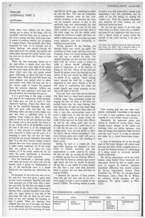
Re-assembly of the hubs was next on our list, and they were first given a good clean up and visual inspection. Bearings and seals were knocked out of the hubs with a hammer and drift. On this job, one needs to take small bites at the cherry when removing a bearing when a proper mandrel is not available; too many blows on one side of the race-rings will only tip them up and cause them to jam and damage the housing, so take it gently. When our bearings were stripped only one out of the eight was found to be sufficiently faulty to warrant changing. As it was driven out of its housing the inner race fell out of the cage, scattering its rollers all over the floor. This was not completely unexpected because when we had commenced stripping on the previous day there was an excessive amount of play in this particular unit, and unfortunately this had allowed the inner race to turn on the axle shaft. Luckily no damage had been done at this early stage, but had the vehicle really needed an overhaul it might well have entailed a replacement axle, or at, the very least some expensive and time consuming rebuilding and machining.
Having checked out the bearings and decided which ones would "go again" the condition of wheel studs and back nuts were inspected. None was found wanting and the next job was to rebuild the hubs. The cleaned bearings and the one new one were filled with the correct grade of grease (a table is shown below). Although the grade is important, so is the amount of grease in the hub. Plenty of the lubricant should be packed round the bearings but the centre of the hub should be filled only to two-thirds of its capacity. Leave enough space around the shaft for a degree of expansion to take place. Failure to do this will result in overheating and make the grease liquefy and create pressure on the seal at the back of the hub.
Once our hubs were built up we checked that there were no sharp burrs around seal rubbing rings. This precaution avoids damaging the new oil seals as the hubs are pushed home onto the inner bearing. Our seal rings were all right but had sharp edges been found they would have been taken off with a very fine carborundum stone and given a slight lead, to help the seal on its way. A light smear of grease round the inside of the seal and the hubs were offered up one by one taking great care not to damage the axle threads. A point here is not to rush the oil seal over its spigot with a straight push. Turn the hub gently to allow the seal to ride up without damaging it. Two extra minutes spent here might well save a set of ruined brake liners and doubling of labour costs.
Setting the hubs is a simple job. The taper-roller bearings are designed to have 0.004 to 0.006in. end-float and this measurement is easily achieved by taking the hub nut fully up, turning the hub gently to displace grease from the bearing. When it is seen that the bearing surfaces have seated right down, the hub nut should be slacked off one flat, or one eighth of a turn; despite the fact that it may seem that excessive slack is present, the end float will then be exactly 0.006in.
I disputed the amount of float present when this job was done and so we set a clock gauge in order to prove a point. It was exactly 0.006in. The locking washer is made in such a way that it provides a vernier style adjustment—very fine alterations can be made to the hub setting by turning the washer over. When the required adjustment was achieved the outer locking nut was fitted and locked up dead.
Do not put any grease in the hub caps when these are fitted. Leave this as additional space for any expansion that may occur. Just a liberal smear of grease round the outside of the outer bearing is all that is required.
Your running gear has now been completely overhauled. According to the maker it is now in mint condition and should be capable of a tour of duty similar to its first.
Remember the important points that should be checked at service times. These include torque settings on the radius rod retaining bolts and spring tightness. And when the brake-wear indicator-teeth are level with the word "worn" it is time to schedule the trailer for a visual brake-lining inspection.
A drop of lubricating oil on the moving parts of the brake linkages will reduce wear and tear and allow all the available power to be used for braking instead of a percentage of it being stolen to overcome partially seized components.
The service departments of all the trailer makers using Rubery Owen Rockwell running gears should be able to supply spare parts on request. If, however, operators experience difficulties they should contact the Service Department, Rubery Owen Rockwell Ltd., PO Box 36, Clevelys Road, Warrington, Lancs, where Mr. K. Wilkes, the company service manager, will give assistance. His phone number is 092532201.