


SENSING THE PROBLEMS
Page 94
Page 95
If you've noticed an error in this article please click here to report it so we can fix it.
Pat Dowsett looks at sensors, the eyes and ears of electronic systems.
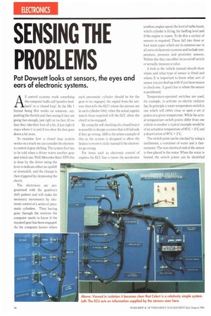
All control systems work something the computer buffs call 'positive feedback' or a 'closed loop'. In the Mk 1 human being this works on someone, say, pushing the throttle and then seeing if they are going fast enough, just right or too fast. If too fast, they take their foot off a bit, if just right it stays where it is and if too slow the foot goes down a bit more.
The electronics are programmed with the gearbox's shift pattern and will make the necessary movements by electronic control of a series of pneumatic cylinders. Then having gone through the motions the computer needs to know if the required gear has been engaged. As the computer knows where each pneumatic cylinder should he for the gear to he engaged, the signal from the sensors then tells the ECll where the pistons are in each cylinder. Only when the actual signals match those required will the ECU allow the clutch to he engaged.
By using the self checking of a closed loop it is possible to design systems that will fail safe if they go wrong. ARS is the prime example of this as the system is designed to allow the brakes to revert to fully manual if the electronics go wrong.
For items such as electronic control of engines the ECU has to know the accelerator position, engine speed, the level of turbo boost, which cylinder is firing, the fuelling level and if the engine is warm. To do this a variety of sensors is required. These fall into three or four main types which are in common use in all sorts of electronic systems and include temperature, pressure and proximity sensors. Within this they can either be an on/off switch or actually measure a value.
A look at the vehicle manual should show where and what type of sensor is fitted and where. It is important to know what sort of sensor you are dealing with if you have reason to check one. A good clue is where the sensor is positioned.
Temperature-operated switches are used, for example, to activate an electric radiator fan. In principle a water temperature switch is one which will either close or open a set of points at a given temperature. While the actual temperature switch points differ from one vehicle to another a typical example would be of an actuation temperature of 95°C ÷ 2°C and a deactivation of 90°C + 2°C.
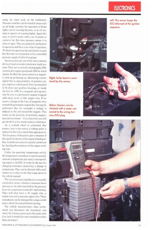
The switch point can be checked by using a multimeter, a container of water and a thermometer. The non-electrical end of the sensor is then placed in the water. When the water is heated, the switch points can he identified using the ohms scale on the multimeter. Pressure switches can be found in areas such as air brake systems, for operation of brake lights and/or warning buzzers, or in oil systems to operate oil warning lights. Again this type of switch works with a set of points or contacts but this time pressure causes it to close or open. They are primarily mechanical in operation and have a set value of operation. To check the operation the multimeter is used, but this time in conjunction with a controlled pressure supply fitted with a gauge.
Speed sensors are one of the most common devices found on modern electronic truck systems. Their use is central to tachographs, EDC systems (for engine speed) and ABS for wheel speeds. In effect the speed sensor is a magnetic pick-up producing an alternating current signal that is representative of gearbox output, engine or wheel speed. Units are installed in flywheel and gearbox housings, or inside the hub for ABS. In a magnetic pick-up (sensor) the core is a permanent magnet wrapped with many turns of fine copper wire. If we cause a change to the lines of magnetic force around the permanent magnet (by moving the perforated disc for example) a voltage is induced in the coil around the magnet. This works on the principle of electricity, magnetism and movement—if you have two you will get the third as in a starter motor or alternator.
As a toothed wheel or perforated disc rotates close to the sensor, a voltage pulse is induced in the coil as metal then gaps pass by. The frequency of the pulses give a measure of the speed of rotation of the engine/wheel/gearbox. A check on a sensor is usually carried out by checking the resistance of the copper winding wire.
Unlike the open/shut temperature switch, the temperature transducer is used to actually measure temperature and send a corrosponding signal to the ECU. It works by the use of a changing resistance caused buy a change in temperature. They can be checked with a multimeter to a value on the ohm range given in the vehicle manual.
The use of pressure transducers is normally restricted to newer vehicles to measure boost pressure in the inlet manifold or the pressure in an air suspension system for load sensing. They will often have a 5V supply wire, a return wire and a pressure signal wire. These transducers can be damaged by using a multi meter: check the manual before starting.
The vehicle manufacturers often recommend you disconnect the transducer and check the wiring system up to that point and, if no fault is found, fit a new transducer rather than checking it.