


A Duplex Easy-change Gearbox
Page 68
If you've noticed an error in this article please click here to report it so we can fix it.
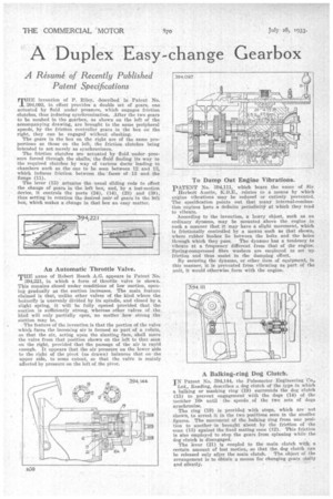
A Re'sume' of Recently Published Patent Specifications TAE invention a P. Riley, described in Patent No. 394,093, in effect provides a double set of gears, one actuated by fluid under pressure, which engages friction clutches, thus inducing synchronization. After the two gears to be meshed in the gearbox, as show-n on the left of the accompanying drawing, are brought to the same peripheral speeds, by the friction controller gears in the box on the right, they can be engaged without clashing.
The gears in the box on the right are of the same proportions as those on the left, the friction clutches being intended to act mcrely as synchronizers.
The friction clutches are actuated by fluid under pressure forced through the shafts, the ifluid finding its way to the required clutches by way of various ducts leading to chambers such as the one to be seen between 12 and 13, which induces friction between the • faces of 13 and the flange (11).
The lever (15) actuates the usual sliding rods to effect the change of gears in the left box, and, by a lost-motion device, it controls the ports (24), (14), (23) and (39), tires setting in rotation the desired pair of gears in the left box, which makes a change in that box an easy matter.
An Automatic Throttle Valve.
THE name of Robert Bosch A.G. appears in Patent No.
394,221, in which a form of throttle valve is shown. This remains closed under conditions of low suction, openink gradually as the suction increases. The main feature claimed is that, unlike other valves of the kind where the butterfly is unevenly divided by its spindle, and closed by n. slight spring, it will be fully opened provided that the suction is sufficiently strong, whereas other valves of the kind will only partially open, no matter 'how strong the suction may be.
The feature of the invention is that the portion of the valve which faces the incoming air is formed as part of a volute, so that the air, acting upon the slanting face, shall move the valve from that position shown on the left to that seen on the right, provided that the passage of the air is rapid enough. It appears that the air pressure on the lower side to the right of the pivot (as drawn) balances that onthe upper side, to some extent, so that the valve is mainly affected by pressure on the left of the pivot.
To Damp Out Engine Vibrations.
PATENT No. 394,111, which bears the name of Sir Herbert Austin, RILE., relates to a means by which engine vibrations may be reduced or entirely prevented. The specification points out that many internal-combustion engines have a definite periodicity at which they tend to vibrate.
According to the invention, a heavy object, such as an ordinary dynamo, may be mounted above the engine in such a manner that it may have a slight movement, which is frictionally controlled by a means such as that shown, where rubber bushes lie between the bolts and the holes through which they pass. The dynamo has a tendency to vibrate at a frequency 'different' from that of the engine.. Spring-compressed fibre washers are employed to set Up friction and thus assist in the damping effect.
By securing the dynamo, or other item of equipment, in this manner, it is prevented from vibrating as part of the unit, it would otherwise .form with the engine.
A Balking-ring Dog Clutch.
IN" Patent No. 394,144, the Pulsometer Engineering Co.,
Ltd., Reading, describes a dog clutch of the type in which a balking or masking ring (19) surrounds the dog clutch (15) to prevent engagement with the dogs (14) of. the member "lCia until the speeds of the two sets of dogs synchronize.
The ring (19) is provided with stops, which are not shown, to arrest it in the two positions seen in the smaller figures. The movement of the balking ring from one position to another is brought about by the friction of the cone (13) against the fixed mating cone (12). This friction is also employed to stop the gears from spinning while -the dog clutch is disengaged.
The lever (21) is coupled to the main clutch with a certain amount of lost motion, so that the. dog clutch can be released only after the main clutch. The object of rhe arrangement is to Obtain a means for changing gears easily and silently.