


Patents Completed.
Page 20
If you've noticed an error in this article please click here to report it so we can fix it.
Another Four-wheel Drive. Detachable Rims. Automatic Change Gearbox.
Complete specificataons of the patents published on this po,ge can be obtained from the Sales Branch, Patent Office, Holborn, W.C., at the cost of sixpence for each specification.
S. E. Branum, W. IT. CARROLL and B. B. SHIVELY, No. 13,766, dated 6th June, 1914.—In this driving gear the steering wheels are mounted so that the steering pivot lies in the plane of contact with the ground, and the power transmission is con centric with the steering pivot so that the movements for steering are not impeded in any way.
The front axle is forked and receives a sleeve within which a stub-axle on the wheel is mounted in ball bearings. This sleeve has vertical pivot pins to permit the steering movements of the wheel, and the wheel is dished so that the steering pivot is vertical and in the plane of the wheel-tread.
The drive is transmitted to a double bevel-wheel mounted concentric with the steering pivot ; the drive is given, to it on the upper set of teeth, and the lower set of teeth mesh with a gear fixed inside the road-wheel.
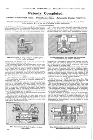
J. W. Lunantootox, No. 29,863, dated 29th December, 1913. —This specification describes an improved construction of detachable-wheel rim.
The tire-carrying-ring is supported at one side of the felinehand by a wedge-shaped projection formed integral therewith, and at the other side by a split clamping ring which is tapered in the opposite direction, and has at, its inner end a hook to permit easy withdrawal of the parts. This clamping ring is pressed home by lugs which are mounted on nuts on the clamp-bolts, so that when the latter are screwed up, the lugs lock the clamping ring in position. The detailed construction of the lugs and bolts is described and illustrated in the specification. The tire is held in place by two side rings which are separate from the tim-carrying-ring ; one of them is held in place by a lug on the main ring, while the other is secured by a split looking ring inserted in a trough shown on the right,hand side of the tire-carrying-ring.
E. P. ',Axis and J. Bur), No. 28,997, dated 16th December, 1913.—In this carburetter a conical heating chamber is provided beneath the float chamber. The fuel passes down from the float chamber into a narrow space separated from the heat
lag agent by a thin sheet of metal which conducts heat efficiently. The fuel passes up through a central jet controlled by a needle valve and mixes with the primary air which enters the jet passage by inclined ports.
This valve also controls the auxiliary air supply, being provided with a set of openings which can be brought to register more or less with similar openings in a surrounding sleeve. The valve is provided at its upper end with a screw thread engaging a second threaded member so that rotation of the valve lifts or lowers the needle valve controlling the fuel inlet ; it also varies the air inlet, but this may be independently varied by turning the second threaded member.
G. H. BRINSON, No. 13,879, dated 8th June, 1914.—This specification describes a change-speed gear in which all the gearwheels may be set in rotation at the same time.
The accompanying perspective thawing indicates the driving shaft, by the belt pulley on the right-hand side. This shaft also carries the first gearwheel, and the remaining three coaxial wheels are mounted to turn freely on the driven shaft.
The countershaft carries.. a corresponding set of gearwheels, and each of these is coupled to the shaft by a ratchet and pawl or other free-wheel device.
If the car is running on top gear, that is to say direct drive, and it is required to change dawn on to the second or third gear, all that is necessary is to engage the selected gear with the driven shaft. The engine drives the countershaft at the desired speed, but as long as the car is running faster, the selected gear on the countershaft overruns its shaft by means of the free-wheel device.