


WHAT IS THE H.P. ?.
Page 8
Page 9
If you've noticed an error in this article please click here to report it so we can fix it.
Simple Methods for Brake-testing the Power of Engines in Repair Works and Garages Without Dismounting from the Chassis.
By R. Waring Brown, A.M.I.A.E.
It is frequently found desirable to ascertain the exact horse-power of an engine, particularly after tuning up in a repair shop,. without going to the extra trouble and expense of dismounting the engine and putting it on the test; bed irethe usual manner.
To diagnose shortcomings, or correctly to ascertain the results of repairs, adjustments to carburetters, or ignition systems and all such experiments, a convenient method for ascertaining the power developed under various conditions, while also allowing available road tests, is in reality indispensable.. Such tests are not the rule in most repair establishments, either through lack of facilities or of confidence in make shift arrangements. Accordingly, the repairs or ex perimental adjustments are permitted to end in doubt as to what has actually been accomplished. Hence it may prove of service to demonstrate methods which have been found of great utility in this direction. The engine in a chassis is usually mounted so that clearances are exceedingly small. It is, therefore, practically certain that a hand-brake oil some type must be utilized for the purpose. While it is not ordinarily recommended that the flywheel be used as a brake drum, an exception can very well be made for tests of mounted motors, if the proper precautions be taken and the tests are not extended over too long,a period. The fact that in some of the best factories the cable brake is still freely used for power determination suggests the simplicity of the method. At the same time this method can only be adopted where clearances are sufficient for the cable.
The arrangementsas used in such works generally comprise am cast-iron stand having two bearings. Mounted in these bearings is a shaft with a broad belt sheave with side flanges, a rope about in. in diameter, wound upon the sheave with the two ends reaching upwards, and attached to two spring scales. The shaft is connected by a coupling to the engine shafWthe motor is started, and when it is warmed up the spring scale on the side where the sheave pulls downward is tightened. The motor then draws the rope around until it begins to rub on the drum on thatside while the other end of the rope loosens. The other spring scale is pulled until it shows,' a few pound loads, by which action the load of the first scale will be -considerably increased. After a few minutes running a condition of equilibrium will be reached which can be recbgnized by a reduction of the motor speed taking place when the second seal e is tightened further. By now deducting the load of the .second scale from that of
the first there is obtained the real load under which the motor has been running, the motor speed being registered by means of a revolution counter. The horse-power is then calculated from the formula 1— B.H.P. P.N.L. x .00019, in which, P = the effective load in lbs. ; N = the revolutions per minute ; L = the effective lever arm in feet, the latter being the leverage with which the load is working or one half the distance from centre to centre of the rope strands.
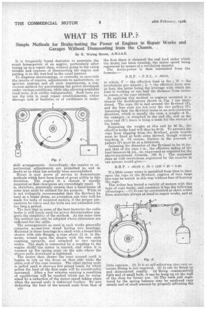
In applying this method to engines mounted in a chassis the modifications shown in Fig. 1 are introduced. The rope (R) is laid around the flywheel (F), and the free ends are led over the two pulleys (P). As-sliming that the flywheel turns in an anti-clockwise direction, which is usually the case, a weight-43 lb., for example—is attached to the end (E), and at the other end (Ek) there is hung a scale for the receipt of the loads.
Supposing the weight at this end be 26 lb., the effective brake load will thus be 20 lb. To prevent the rope from slipping from the flywheel, guide boards must be fixed at both sides thereof, though without touching it. Of course, friction in the journals of pulleys (P) must be at a. minimum.
Assuming the diameter of the flywheel to be 18 ins. and that of the rope 1 in., the effective, radius of the load becomes gi ins., or, expressed as required for the above-mentioned formula, .790 ft. ! The supposed ,data at 1150 revolutions registered by the counter in one minute would give:— B.H.P. = .00019 x .79 X 1150 X 20 3.45.
If a little soapy water is sprinkled from time to time upon the rope or the flywheel, engines of very large .ize may be tested in this way without fear of burning the rope. The writer has tested a variety of motors with this type of rope brake, and considers it has the following advantages :—(l) It can be constructed at short notice from materials always at hand in repair works, and at
little expense. (2) It is so self-adjusting that very ac curate fitting is not required. (3) It can be fitted up and dismounted readily. (4) Being comparatively light and of small bulk, it can be hung up on the wall of the shop for future use. (5) The back pull registered by the spring balance may be rendered very steady and of small amount by properly adiusting the
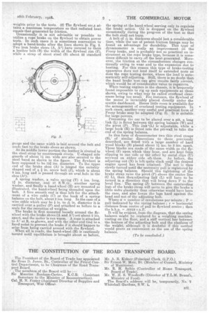
weights prior to the tests. (6) The flywheel soca attains a maximum temperature so that radiated heat equals that generated by friction. Occasionally it is not advisable or possible to utilize a rope brake on the flywheel to obtain power tests. In such cases it is sometimes convenient to adopt a band-brake after the lines shown in Fig. 2. Two iron brake shoes (A, A-') have secured to them a leather belt (B) the width of the flywheel rim (F), while a strap of sheet steel (S) about 22 standard gauge and the same width is laid around the belt and made fast to the brake shoes as shown.
At its middle lower portion the leather is riveted to the steel strap by countersunk rivets. U-shaped side guards of about 1.?si ins. wide are alsosecured to the steel band as shown in the figure. The flywheel is here supposed to be 15f ins. diameter. To the iippei end of the brake shoe (A) is hinged the suitably. shaped end of a in. screw bolt (.1), which is about 8 ins, long and is passed through an oval hole in the shoe (Al).
A spring washer, a valve spring (V) 4 ins. long, 11 in. diameter, and 10 S.W.G.another spring
'
washer and finally a hand-wheel (Ii) are mounted as illustrated, the hanclswheel being threaded upon the bolt. A free smooth end is thus left for the attachment of a wire cable (C) or the hook of a spring balance on the bolt, about 2 ins. long. In the case of a wire cable which may be * in. to--t-s in. diameter it is carried over a pulley (P) and attached as before to a scale for the reception of weights.
The brake is first mounted loosely around the flywheel with the brake shoes (A and Al) set about 2 ins. apart, and the motor is run warm. A rope is attached to Al at R, as ohown, and with the other end tied to a fixed.point to preventthe brake if it should happen to seize from being carried around with the flywheel. When all is ready, the hand-wheel (H) is cautiously turned until equilibrium is brought about as before,
the spring at the hand-wheel serving only to regulate the brake. action. Oil is dropped on the flywheel occasionally during the progress of the -test so that the belt shall not burn.
belt of s's in. thickness should last a considerable time, while the use of patent friction linings may be found an advantage for durability. This type of dynamometer is really an improvement on the Prony brake, and is probably not sti practical an instrument as the rope brake type, because it is sometimes difficult to carry off the heat generated. MoreOver, the friction at the circumference changes continually owing to wear and to the expansion due to heating. For this reason this type of brake-testing apparatus does not lend itself to extended tests as does the rope testing device, *here the load is automatically self-adjusting. Still; there is no doubt that the band brake test can give results fairly correct, which would be of eonsiderable value to repairers. When testing engines in the chassis, it is frequently found impossible to rig up such equipments as those shown, owing to what may be called overhead clearances being too small.. For, instance, the flywheel of the motor is invariably placed directly under the scuttle dashboard. Hence little room is available for the arrangement of overhead testing equipment. In such cases, another .very useful and practical form of Prony brake may be adopted (Fig. 3). It is suitable for large powers.
Presuming the car to be placed over a pit., a long link (L) is fitted between the spring balance (W) and the pivot (P). This link '(L) is adjustable, while a large hook (H) is fitted into the pit-wall to take the end of the spring balance.
In this -form of dynamometer two thin steel straps (S), ' ofsimilar dimensions to those previously described, are fittedwith a large number of hard wood blocks (B) placed about 11ins. to 2 ins. apart. Those blocks are made of the same width as the flywheel. (F) upon, which they bear, and are kept from slipping to one side or the other by metal clips (U) screwed on either side of them. As before, the adjusting nut (N) is left quite slack unil the desired engine speed has been attained. The nut is then slowly turned until the necessary pull is registered by the spring balance. Should this tightening of the brake strap raise, the pivot (P) above the centre line (C L), then thes.,adjesting link (L) will have to be turned in a direction that will bring down P to the level line.. The spring (J) between the outstanding lugs of the brake-strap will serve to give the brake -a little mcfre elasticity than otherwise would have been the case, and also keeps the lugs hard against the head and nut of the adjusting bolt.
_ Where n = number of revolutions per minute ; P pull-indicated by the spring balance ; r = horizontal distance from centre of pull to flywheel centre ; then the b.h.p. — .00019 r.n.P.
It will be evident, from the diagram, that. the spring balance might bereplaced by a weighing machine, resting.on the floor, and a stiff vertical bar between the bottom of the adjusting bolt and the Platform of the weight, although it is doubtful if this method would prove as convenient as the use of the spring balance.
(To be concluded.)