


The Latest Clutch Practice
Page 52
If you've noticed an error in this article please click here to report it so we can fix it.
A Resume' of Recently. Published Patent Specifications, Copies of which, Price • ,ls„ can be Obtained from the
Patent Office •
IMPROVEMENTS intended to damp lout transmitted vibrations are shown in patent No. 419,410, by the Borg and Beck Co., and H. V. Reed, both of 6,558 South Menard Avenue, Chicago, U.S.A. In this design the hub member. drives the frictiOn member through the medium of a number of springs which serve to key the two members together. The springs are not all similar, however, being arranged in two sets, those shown at (1). completely filling their slots, and thus transmitting the drive at all times, whilst the others indicated at (2) can be moved a small amount in their slots before coming under compression. By this means an increasing cushioning effect is brought into play as the torque rises.
The Prevention of Injection-nozzle Overheating.
E'RO1V1 S. A. Adolphe Sa,urer, Arbon, Switzerland, comes patent No. 419,265, giving details of a proposed addition to an injection nozzle for the purpose of minimizing the evils of overheating. The specification states that as an injection nozzle usually projects well into the combustion chamber, it may easily reach such a temperature as to cause jamming of the needle and premature evaporation of the fuel.
The schemeput forward to remedy this is to surround the point of the nozzle with a sleeve (2) having a flange (1) pressed into contact with the water-cooled cylinder head. The object is to conduct the heat away from the nozzle, and, in order to ensure a close fit, it is proposed to slit the sleeve in four places, and then to spring the sections slightly inwards to grip the nozzle.
A Roller-bearing Gudgeon-pin.
A PISTON and connecting-rod assembly, having roller bearings fitted to the small end, is shown in patent No. 416,831 by A. B. Svenska icullagerfabriken, 17, Artillerigatan, Gothenburg, Sweden. The outstanding feature is the manner in which the diameter over the rollers is made subn42
stantially equal to that of the connecting-rod bore, thus making for ease of assembly.
The drawing shows the 'Viers housed in a groove (2) formed in the gudgeonpin, this being of such a depth that the addition of the rollers brings the diameter to the same dimension as that of the plain portion (1). A , hardened sleeve (3) is in
T. %N. 'Xi...,
.1i t
• S ,dis• terposed to take the wear of the rollers.
The specification also describes the met hod of assembly a n d mentions that a suitable scheme would be to insert the gudgeon-pin and rollers direct from the package in which they are supplied, a special assembling sleeve doing duty as a package. By this means little skill would be required to insert a new pin, whilst dirtand other foreign matter would have no chance to enter.
An Independently Sprung Driving Axle.
ALTHOUGH there are many ways of arranging for the independent
suspension of the front wheels of a vehicle, the rear wheels present more difficulty, owing to the driving mechanism. A design of rear, axle of this type is shown in patent No. 418,402, by J. Zubaty, Schwarzova 15, Plzen, Czechoslovakia. The drawing shows one 'of
several designs. this case the axle tube is pivoted on to the axle caning-at two points' (1), whilst the live axle is provided with a universal joint (3) on the same.axis. Oil-tightness is achieved by a spheridal waSher held up to the casing by .a spring (2): The Pivots (1) 'are bushed with robber," 'to avOid the need for lubrication.
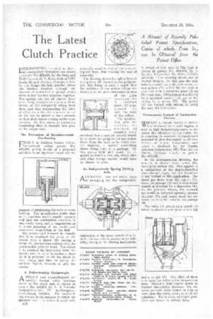
Thermostatic Control of Carburetter Heaters.
WWHILST a hot-air intake is doubtless beneficial for a cold engine, it may at high temperatures serve to decrease the efficiency of the engine by attenuating the mixture. A contrivance intended to give due regard to all conditions of engine temperature and speed is disclosed by the Bendix Aviation Corporation, 105, West Adams Street, Chicago, U.S.A., in patent No. 417,522.
In the accompanying drawing, the mixture is drawn down tubes (8), leaving by orifices (9). This applies to a carburetter of the double-barrelled down-draught type, but the invention is not limited to this application. Exhaust gas flows from the engine (1), down the passage (2) and is then either passed or diverted by a flap-valve (4), In the position shown, the exhaust gas would be deflected upwards, around chamber (7), and would reach the exhaust outlet at the bottom, via passage (6).
The valve (4) pivots on a spindle to which is attached a bi-metallic coil (5), and a weight (3). The effect, of these is to open the valve as the temperature rises. Should a high 'engine speed be reached meanwhile, however, the exhaust pressure alone would be able to blow open the valve, owing to its slight unbalance. The midway and open positions are shown in dotted lines.