


Flexible Coupling Employing Bonded Rubber
Page 34
If you've noticed an error in this article please click here to report it so we can fix it.
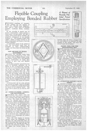
A Resume of Recently Pubfished Patent . Specifications FLEXIBLE couplings for transrnission systems are the subject of patent -No. 524,440 from Silentbloc, Ltd., and V. Trier, both of Victoria Gardens, Ladbroke Road, London, W.11.
In the drawing is shown one of several constructions, which features a three-armed driving spider (3) asR1 similar three-armed driven member (2) angularly interspaced in an annular housing (1). The housing is filled with rubber, which is firmly bonded to all three components and forms a firm but flexible assembly.
A noteworthy point of the patent is that the -t,wo-armed units may be arranged to meet under-excessive torque, and thus limit the stress on the rubber.
NEW METHOD OF BRAKE • ADJUSTMENT DATENT No. 524,363 comes from 1 Automotive Products Co., Ltd., and G. Gates, both of Brock House, Langham Street, London, W.1, and discloses a new construction of brake shoe intended to give easy and efficient ad j ustment.
A two-shoe assembly operated by two pairs of hydraulic spreaders (5) is shown in the accompanying drawing. One end (1) of each shoe abuts directly on to the stop pillars, but the other end carries a separate piece (3). This is slidably attached to the web of the 'shov... and fits snugly under the facing flange, so that in effect it becomes part of the shoe. It can, however, be slid along the web, resulting in an increase of the effective length of the shoe, and it is this feature that forms the adjustment.
A friction-bolt (4) in a slot permits the increase in length, which is brought about by pulling in a wedge-shaped nut by means of an external screw. The latter unit is shown in an end-on view at 2.
AN UPPER-CYLINDER LUBRICATOR FOR STARTING
RESEARCH into engine wear has revealed that this is at a maximum When starting from cold, and a device to reduce this forms the subject of patent No. 524,447 from C. and S. Clementson, Malmo-Limhamn, Sweden.
The patent shows an automatic injector for feeding a' small quantity of lubricating oil to the induction pipe when starting and running cold. An oil tank has at its lower end a measuring container (6), which is open to the atmosphere via a tube (4). A movable suction-pipe (7) carries a shut-off valve (5) at its lower 'end, whilst the top is connected to a diaphragm (3) subject to intake suction. When the cold 'engine is started, suction causes the diaphragm to lift the pipe (7); this closes the valve (5) and at the same time sucks the oil from the container (6) through the pipe (7) and into the induction system. When the engine has become warm a bi
metallic strip (2) frees a trapped ball (1) and allows it to obstruct the pipe leading to the intake, and thus the device is put out of action.
HANDY TOOL FOR THE MAINTENANCE MAN WHEN replacing overhead valves in IT a cylinder head it is necessary to support them from below while the valve springs are compressed and assembled. A tool to facilitate this Operation, is shown in patent No. 524,401 by R. Parsons, Swandean Gar;ge, Durrington, Sussex.
This inventor suggests the use of a special frame, on which the cylinder head is to be placed, the frame having upstanding pillars at the points where the valves 'are located. The head is then clamped down, and the valves are thus firmly held from sliding down. The patent describes a universal device, consisting of an angle-iron frame (3) with a central slot, in which movable blocks (2), held by spring-loaded bolts, can be moved to any desired position. When the blocks have been suitably positioned, the head is held down by a strap (1).
AN ATTRACTIVE ROTARY-VALVE , • DESIGN
A DESIGN of rotary valve, sintable 1—k for an engine with in-line cylinders, comes in patent No. 524,424 from H. McLaren, 84, Union Street, North Brighton, Victoria, Australia.
In this scheme the cylinders are individuallyurged in an upward direction by means of springs (7) under the bottom flanges. This creates the sealing pressure upon the working surface of the rotary valve (3), the abutment being a water-jacketed semi-circular cover (2). Only the tubular valve (3) revolves, the innermost portion, which consists of a water-cooled girder member (1), being stationary.
Between the girder (I) and the inside of the valve barrel is a number of spring-loaded shoes (4), one to each cylinder, and these form an induction seal, the inlet passage being a bore (9) throughout all the shoes. Each cylinder has its own exhaust outlet (6), which is connected with the working space by a groove (5) in the valve barrel. Similarly, ports (10) in the barrel connect
the induction passage (9). .
The sparking plug, is housed in a pocket (8) and is connected to the cylinder only for a short time, ivhile one of the ports (11) bridges the intervening wall.