


AN ENGINE-OPERATED BRAKE GEAR.
Page 34
If you've noticed an error in this article please click here to report it so we can fix it.
A Résumé of Recently Published Patents.
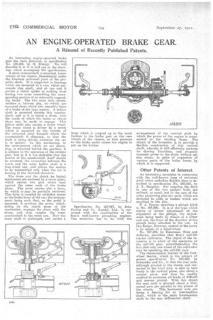
An interesting engine-operated brake gear has been patented, in specification No. 158,205, by M. Birkigt. We will describe it as it is laid out in the drawings which accompany the specification.
A short countershaft is mounted, transverselyof the chassis, immediately -under the foremost universal joint of the propeller shaft. It is supported in bearings which are mounted in a case which surrounds' that shaft, and at one end it carries a clutch spider or rocking lever having two arms resembling the wirespending portion of an internally-expand ing brake. The two arms each'accommodate a fulcrum pin, 'on -which are mounted shoes which also resemble those of 'a brake of the type named. A hollow shaft is mounted outside this countershaft, and to it is keyed a drum, with the inside of which the brake Or clutch shoes may be made to engage. This .hellow shaft also carries a worm wheel. The worm wheel ,is driven by a worm which is mounted on the outside of the universal joint beneath which the countershaft is disposed,' so that the shaft is being driven whenever the car is in motion. As this mechanism, in the arrangement which we are discussing, is mounted behind the gearbox, it is subject to the operation of the reverse gear, and as it is not, desirable that the motion of the countershaft itself should be reversed, the connection between the worm and the outer hollow shaft is a free-wheel one, and allows the motion to be transmitted only when the car is moving in the forward direction.
The drum and the clutch (or brake) mechanism are enclosed by a cover plate, which carries two pins which bear against the outer ends of 'the brake shoes. The cover carries also a lever, by which it ,.may be partially revolved. This lever is coupled by orthodox means to the brake lever of the car, the arrangement being such that, as the pedal is operated, it revolves the cover, which, acting on the clutch shoes of the mechanism, engages the shoes with the drum, and thus couples the Miter countershaft to the outer one. Now the inner shaft is prolonged, and carries a; lever which is coupled up in the usual fashion to the brake gear on therear wheels of the chassis, 131) that pressure on the brake pedal causes the -engine to put on the 'brakes.
Specification No. 167,947, by John Fowler and Co. (Deeds), Ltd., is concerned with the construction of the firm's well-known ploughing engines. The invention has to do with the
arrangement of the vertical shaft by which the power of the engine is transmitted to the winding drum. The object of the invention is to provide a flexible, construction of this vertical shaft, whereby it Will efficiently perform its driving functions, and properly transmit power to the drum without undue strain, in spite of expansion of various parts of the boiler frame. by which it is eupported.
Other Patents of Interest. .„
An interestinr, invention in connection with the well-awn type of universal joint which embodies flexible discs is described in specification No. 168,016, by J. Y. 'Sangster. For coupling the discs to one of the two spiders bolts are utilized, as usual, but in the case of the other projecting pins are used, which are designed to slide in bushes which are mounted in the disc.
P, 'J. Frayne describes a plough hitch in No. 167,986. It is of thetype which allows of lateral adjustment of the alignment of the plough, the adjustment being made by means of a screw and nut, the front of the drawbar of the plough being attached to the nut. In this design, however, control of the screw is by means of a hand-wheel.
No. 167,896, by Ransomes, Sims and Jefferies, describes that firm's 'self-lift tractor cultivator. The object of the invehtion is to -allow of the operation of the self-lift gear, notwithstanding the fact.that only one wheel of the cultivator may be' operating the .sel&lift rack.
'The Characteristie feature of the fourwheel tractor, which iS the 'subject 'Of patent specification No. .163,689, by Schneider and.Co., is that the rear axle, although pivoted to -the chaksis and conmected to the front axle, is able to turn freely in the vertical plane, also about a central pivot, and thus be readily enabled to surmount all kinds of difficult and uneven ground. With this object the rear axle is pivoted about a horizontal axle pin parallel to the planes of
the wheels. This horizontal axle pin forms a bearing for an intermediate -shaft, which is the .main transmission Aliiiit to the rear differential haft;. •