 1
1 2
2 3
3 4
4 5
5 6
6 7
7 8
8 9
9 10
10 11
11 12
12 13
13 14
14 15
15 16
16 17
17 18
18 19
19 20
20 21
21 22
22 23
23 24
24 25
25 26
26 27
27 28
28 29
29 30
30 31
31 32
32 33
33 34
34 35
35 36
36 37
37 38
38 39
39 40
40 41
41 42
42 43
43 44
44 45
45 46
46 47
47 48
48 49
49 50
50 51
51 52
52 53
53 54
54 55
55 56
56 57
57 58
58 59
59 60
60 61
61 62
62 63
63 64
64 65
65 66
66 67
67 68
68 69
69 70
70 71
71 72
72 73
73 74
74 75
75 76
76 77
77 78
78 79
79 80
80 81
81 82
82 83
83 84
84 85
85 86
86 87
87 88
88 89
89 90
90 91
91 92
92 93
93 94
94 95
95 96
96 97
97 98
98 99
99 100
100 101
101 102
102 103
103 104
104 105
105 106
106 107
107 108
108 109
109 110
110 111
111 112
112 113
113 114
114 115
115 116
116 117
117 118
118 119
119 120
120 121
121 122
122 123
123 124
124 125
125 126
126 127
127 128
128 129
129 130
130 131
131 132
132 133
133 134
134 135
135 136
136 137
137 138
138 139
139 140
140 141
141 142
142 143
143 144
144 145
145 146
146 147
147 148
148 149
149 150
150 151
151 152
152 153
153 154
154 155
155 156
156 157
157 158
158 159
159 160
160 161
161 162
162 163
163 164
164 165
165 166
166 167
167 168
168 169
169 170
170 171
171 172
172 ROUTINE FIT
Page 50
If you've noticed an error in this article please click here to report it so we can fix it.
Power for the Transcover 9000 system feeds from the batteries to a 24V relay and circuit breaker unit, which is usually mounted adjacent to the vehicle batteries. From there, power cables are routed through to the cab control switch and, via a circuitous route, to the Superwinch directdrive electric motor mounted outboard of the body's front corner.
4 Spring hanger brackets for the tubular canopy arms are welded to each side of the body. slightly behind the halfway mark. Short side-frame sections are attached to the pivot pins and secured at each side by three bolts. Each rear half is cranked downwards at the curved ends that accept the single lateral spar linking the two side tubes. This forms the U-shaped sheet-rolling frame. With the frame tubes trimmed to length, ends drilled and all rough edges removed, the structure is bolted together.
• The extruded aluminium roller shaft spans the hopper-like tray In the front bulkhead. A steel spindle is fitted to the nearside end, and is located in a fixed bush while the other end of the roller attaches to the electric motor's drive shaft that protrudes through the hopper side. Each end of the main shaft is secured by a locking bolt and spring washer.
With the frame tailored to the body size, the 7.46m x2.28m (24.5ftx73ft) sheet is opened up and attaches to the roller. To fit it (or renew it), begin at the front end. The reinforced spline, sewn into the end of the sheet, is carefully threaded into the shaft and pulled along the longitudinal slots, so that the sheet is in a central position.
With the sheet fitted, check the operation to see that it Is located centrally, that the material furls neatly and that the frame sits correctly on the travel stops. Weld extra stays to the mudwings and new brackets for the side marker/Indicator lights. After fitting and connecting them, clean up all the welded areas and apply the grey primer.
A full length of steel conduit Is welded to the underside of the body, and this carries the Transcover's power supply. The wires are fed from the battery, across the frame then along the inside of the chassis to the rear of the body, through the piping to the front and up to the winder motor.
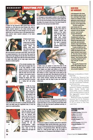
The sheet system's powerful drive motor is mounted against the outside of the body's front bulkhead, ready to couple to the sheetrolling shaft located Inside. Secured by three 5/16 UNC bolts, the twin flex cable is connected and a weatherproof protective shield Is then attached.
Buffer stops are needed to arrest the travel of the sheeting frame. At the rear, mounting brackets are welded to the tailgate and rubber pads bolted on, but the front stops have to be positioned carefully in the bulkhead tray. One method is to link a sturdy rope to the centre of the frame and to the roller shaft. Then using the cab switch, the motorised shaft pulls the frame over to the front, against return spring pressure. Ensuring that there's adequate roller clearance, weld the stops In place and attach the rubber pads.
At the rear, the frame is unbolted at one side to allow it to enter the loop In the sheet. It's important to smooth off any rough metal edges so as not to fray the material either when fitting or In use. Once the sheet Is positioned centrally, rebolt the frame together.
Transcover supplies its sheeting system kits to operators and bodybuilders alike. Each kit comes with a clear and concise set of fitting instructions that are well within the understanding of any experienced artisan. Most kits can also be fitted on a while-you-wait basis at the TTS facility at Swanley, Kent, or at Thompsons In New Addington, Croydon.