


Patents Completed.
Page 30
If you've noticed an error in this article please click here to report it so we can fix it.
Fire-engine Transmission.
Austrian Daimler Motor Co. Ltd.—No. 8068/12, dated under International Convention, 10th April, 1911.—According to this invention a motor fire-engine with a rotary pump driven off the motor shaft, is so arranged that the pump-shaft is hollow, and surrounds the driving-shaft. This construction enables the pump to be placed between the clutch and the change-speed gear. The practical result of this is that the pump can be arranged under the driver's seat, that is to say, a space which has hitherto been inadequately occupied, is utilized in a practical manner, and the pump is readily accessible. In one construction a dog-clutch is secured on the hollow pumpelpindle for engaging with a similar clutch on the intermediate portion of the driving-shaft. With this arrangement the pump is driven at the same speed ae the engine, but if it be wished, a geared connection may be used whereby the pump can be driven at a speed either higher or lower than that of the engine.
An Accessible Carburetter.
Sir W. H. Bailey, A. J. Bailey and W. B. Dale.—No. 507, dated 4th January, 1912.—The object of this inventien is to provide a carburetter in which the several parts of the jet and the cheketube shall be visible and easily accessible from the intake or atmospheric side of the choke-tube, and whereby inspection and adjustment may be effected chile the engine is running. The mixing chamber is farmed in a casing with an opening on its upper side in which the choke-tube is fitted. A conduit formed in the base portion of the casing conveys the fuel to a jet, which is secured in the
bottom of the casing, and this extends upwards co-axially with the choke-tube. The jet is conveniently formed as a plug, with longitudinal and transverse openings, screwed into a vertical tube so as to be adjustable. Any form of jet may be used, and auxiliary airdnlets may be provided if required.
Horsehair Tires.
A. Folliet-Mieusset and R. van de Casteele.—No. 27,506, dated 7th Decem ber, 1911.—This invention relates to resilient tires, and consists in making the tires of sheets or bands of horse-hair which has been felted by compression either when hot or cold, and then winding it round a core. Various tires are described in this specification. The core may be formed of a solid or hollow metal ring, or it may be an india-rubber airchamber, or may itself he compressed horse-hair. The compressed bands may be wound on in several layers, with or without the interposition of thin metal bards ; if desired they may be wound loosely to assist the elastic working of the whole. A canvas or like cover is finally secured on the tire. In an alter native eonsti int ion an elastic tread is provided by winding successive parallel layers in an annular groove as illustrated.
A Gearbox Control.
0. Bramley Moore.—No. 22,459, dated 11th October, 1911.—This specification describes operating gear for change-speed gearboxes, and is particularly adapted to the gearbox described in Patent Na. 6859 of 1905. The driving shaft and driven shaft in the gearbox are in line, and the countershaft, with three gears fixed thereon, is situated below them. The sleeve carrying a gear extends over the adjacent ends of the driving and driven shafts, and can be coupled to either by slidable dog-clutches. One gear wheel loose on the driving-shaft, and another loose on the driven-shaft, and each capable of being clutched to their shafts by a suitable dog-clutch, enable four speeds and a reverse to be obtained. The control is effected by striking-rods coupled to levers fixed on sleeves on the spindle of the changespeed operating handle. In the construction illustrated there are five sleeves, two of which are fixed to the shaft., and three are mounted loosely thereon, but prevented from rotation by a key engaging the casing. The operating-levers are prevented from moving sideways by suitable guides, and are engaged by one of the two fixed sleeves for operating, or by one of the three loose sleeves for locking in their inoperative positions.
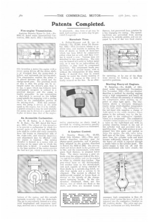
Starting Heavy-oil Engines.
W. Babsilber.—No. 25,604, of 1911, dated under International Convention, 21st November, 1910.—This specification describes a method for starting engines rising a hit compression and heavy oil as fuel, wit out the necessity of reducing the compression when starting up on petrol or other light spirit. The illustration shows a two-cycle three-port engine using crank-chamber compression for the light spirit. The carburetter on the left-hand side supplies a charge of light spirit to the crank chamber which passes in the ordinary way by the bypass port to the combustion chamber, where it is compressed. The combustion chamber communicates at the top through a valve on the right-hand side with an annular chamber formed in the end of the cylinder wall and provided with a sparking plug. The light mixture is compressed into this space and ignited to drive the engine, the side valve being held open all the time. After running a short time the cylinder walls and head become sufficiently heated to vaporize the heavy oil which is injected through a needle valve in the cylinder head. The petrol supply is then cut off and the above-mentioned side valve closed ; the
necessary high compression is then obtained which ignites the heavy oil as it is injected into the combustion chamber on the working stroke. The valve and controlling mechanism are fully described.