


Automatic Chassis Lubrication
Page 58
If you've noticed an error in this article please click here to report it so we can fix it.
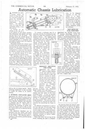
A SYSTEM for hibri. I-1 eating points on
chassis at long, but regu lar, intervals is shown in patent No. 684,488, by Rolls-Royce, Ltd., Nightingale R o a d, Derby. The operating cycle is a long one, 100 road-miles being a suitable period.
A feature of the scheme is the use of a trctal bellows as the piston member, thus dispensing with glands and other moving seals in the oil pump. The drawing shows the general layout of the pump and driving gear. The latter, shown generally at 1, comprises sufficient pairs of gears to give the required low-working speed.
The pump consists of a closed vessel (2) fitted with inlet and discharge valves, and housing the metal bellows (3). The bellows is alternately expanded and contracted by a crank (4), thus altering the effective volume of the pump chamber. A powerful spring (5) is compressed during the suction stroke.
The operating crank is not directly connected with the gearing, but is fitted with a lost-motion device 'Which permits the crank to remain stationary for much of its time. When it does turn, imme diately it gets over dead-centre, the compressed spring takes command and delivers the oil charge rapidly. Handoperating mechanism is also provided to enable the pump to be quickly primed.
A DUMPING CONTAINER BODY
PATET•4 No. 684,497, comes from a Dutch Government Department, De Directie van de Staatsmijnen in Limburg, Heerlen, Holland, and describes a container and the vehicle used in
conjunction with it. The aim is to facilitate the handling of goods that cannot be tipped, such as tiles, so that the vehicle need not be detained during unloading.
The ccontainers described can be detached from the vehicle, and stood on the ground using the motive power of the vehicle. The drawing shows a container in the midway position during the operation.
A40 To unload, a hydraulic ram (1) is powered, and this, by pressing on camplates (2) raises the container into the position shown. The tipping action continues until the legs (3) reach the groand, biting into it with teeth (4). If the vehicle now be slowly driven forward, the legs remain on the ground and the container slowly descends, finally running off the vehicle on rollers (5) working in guides (6) attached to the vehicle.
During this operation, front legs (7) are let down to support the container at the front when the vehiclemoves away. To re-load, the vehicle has only to be backed under the container, when the converse of the foregoing oPerations takes place.
RESILIENT MOUNTING FOR TANKS DATENT No. 684,197 refers to tanker vehicles of the type used for transporting liquids in bulk, and shows a method of attaching the tank so as to permit flexing of the frame without stressing the tank, which is a very rigid member. The patentees are Thompson Brothers (Bilston), Ltd., Bilston, Staff s, Motor Services (London), Ltd., Southfield Road, London, W.4, and others. The drawing shows a cross-section of chassis and tank taken at the front
mounting point. A pin (I) projects from a chassis cross-member and a bracket on the tank strap (2) encircles the pin, a compressed rubber sleeve being interposed. This acts as a pivot in a limited way, locating the tank with certainty but permitting the frame to twist.
An identical arrangement is used at the rear end also, the pivot-pin being co-axial with the one at the front. To act as a stop to the rocking movement, each encircling strap is provided with downward brackets (3) fitted with foot members recessed to receive rubber cushioning pads (4).
These can either rest on top of the frame, stressing the pads in cornpres sion, or be disposed sideways, so that the rubber is in shear. Similar fittings are used at intermediate points if required, but as the distortion in the middle of frame is less, simple rubber sandwich joints are sufficient.
NEW IDEAS ON FUEL INJECTION
PATENT No. 682,496, comes from Inconex Handelsges. m.b.H. für Industrielle Procliv.te-KonstructiorienExport, 3, Robert=Bosch-Strasse, Stungart, Germany, and shows a new kind of injector, said to open the way. to the building of smaller and faster oil engines, drid permitting the use of much ' heavier fuel.
The basic principle is this: The charge of fuel is stored in the injector during the preceding firing stroke, and is thereby heated. The fuel is raised to a temperature above its vaporizing point, but the pump pressure is high enough to prevent it boiling.
When injection occurs, the comparatively lower pressure in the cylinder causes the fuel to turn into vapour imniediately, a state of affairs which makes for good intermixture with the air. In addition, the high temperature is said to set up a cracking action -which changes the nature of the fuel into a lighter type.
The drawing shows the injector used, the chief point of which is the provision of fins (1) on the tip, to absorb heat from the combustion. The fin area must be carefully chosen to transmit the correct amount of heat, and for starting purposes, an electric heater may be built into the fins. With heavy oil fuels, a pressure of from five to 10 atmospheres above that in the cylinder is said to give good results.