


Turbocharl for Small Engines
Page 40
Page 41
Page 42
Page 45
If you've noticed an error in this article please click here to report it so we can fix it.
TURBOCHARGING of engines of over about 300 b.h. output dates back to the very beginning of this centu with work carried out by Dr. Alfred J. Buchi, and th practice is now commonplace on large engines, but the turb charging of small engines, and in particular the automoti. type, made virtually no progress until after the 1939-45 wti This was because of several functional disadvantages , existing types of turbocharger applicable to small engines.
Since the War the position has changed and the followil conditions apply: 1. The adoption of radial-flow turbines—in effect, centrifug compressors running reversed—made it possible to reta reasonably high efficiencies for much smaller flow quantiti4 Widespread adoption of the radial-flow turbine, howev( depended on another factor, this being the ability to ca the rotor in one piece to very fine limits, and this has be made possible by the commercial development of the lost-wl casting process, hitherto restricted to very specializi applications.
2. Plain bearings, lubricated from the engine oil supply, we adopted in place of ball or roller bearings. This impli higher frictional losses, but life is extended very considerab to equal the life of the engine bearings. Rubbing speeds a relatively low by steam-turbine standards, whilst loadings a so low that the major problem to be solved was the suppressi■ of oil-film instability or "whirl -.
3. Intense research into high-temperature alloys for the airerE gas turbine provided materials that would operate at signi cantly higher temperatures than before, fully matching t' needs of smaller engines.
4. Drastic simplification of design was undertaken and t practice of "repair by replacement" is now widely adopte This ieflects the difference in philosophy between the desig of automotive diesel engines and, for example, large mani diesel engines.
The small turbocharger, which for the purposes of ti paper is taken to be a unit with a compressor-wheel diamel of less than 7 in.. has thus gradually emerged since the m and is now a standard accessory on many production engin. The requirements that must be met by the small turbocharg number six, and all are essential.
The blower mbst be light enough to be supported on t
engine exhaust manifold but robust enough to withstand all service •conditions that the engine will be exposed to, such as extremes of temperature and altitude, severe external vibratien and rapid load changes. It must be foolproof in operation and require no special starting or stopping techniques. It should not require any maintenance additional to that normally given to the engine, and minor servicing should be confined to the intervals when engine top overhauls are normally required. It should be capable of being overhauled in the average workshop without special equipment, using factorysupplied spare parts where needed.
Irscost should not cause the cost per horsepower of the turbocharged engine to exceed that of the normally-aspirated engine. Advantages of increased power weight and power : volume ratios, together with reduced specific fuel consumption, can thus be fully exploited.
he major overhaul period of the turbocharger should equal or better the major overhaul period of the engine: this may vary from less than 5,000 up to 20,000 hours depending on the t■pe of duty.
Hie user must also play his part, and will find that he will al.eays obtain good service experience from proved engines eempped with .small turbochargers providing that he does not meddle with the installation (particularly the fuel setting) and that he follows the engine makers' maintenance and servicing instra CtiO Os.
INSTALLATION It has been found that there is always a great temptation for the user of a turbocharged engine to increase the fuel-pump settiee and obtain more power. Maybe he has tried this on normally aspirated engines, but has been defeated by the apNarance of black exhaust smoke: the turbocharged engine will not produce nearly so much smoke if given excess fuel at full speed, but the user will destroy the engine and turbocharger in a very short time if he does this.
When he engine maker installs a turbocharger on an engine, various fundamentals must be observed, although these are not always entirely appreciated. First, the turbocharger is almost always mounted on the engine by bolting the turbine
inlet flange directly onto the exhaust manifold. Because of thermal expansion of the manifold, the turbocharger may move up to 0.4 in. relative to the engine between the -cold and hot conditions, and it is therefore vital to provide.some flexibilit for the remaining connections to the turbocharger. A satisfactory method of providing flexibility at the turbine outlet is to fit a short len.gth of sliding pipework with its downstream end supported from the engine. This pipe can also usefully be employed as a diffuser to recover some of the velocity energy in the turbine exhaust.
PROVIDING FOR FLEXING Sufficient flexibility in the compressor-discharge connection
can be provided by rubber hose connections at the ends of a. short length of pipe in the delivery duct. A straight pipe should be employed, since if a. bent pipe. ia usedthere is a danger of it being blown off. Similarly, flexibility should be provided at the compressor inlet by rubber "hinges". in the pipe. The lubricating-oil pipes will normally be long enough
to flex by themselves, but this must be checked.
Since the turbocharged engine will use up.to twice as much
air as the normally aspirated engine, it is necessary to provide air filters and exhaust pipes of adequate size. "A turbocharged engine is more sensitive to inlet and exhaust pressure losses than a naturally aspirated engine.
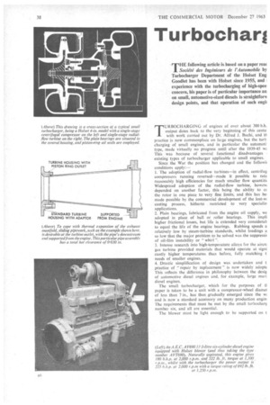
A cross-section of a typical small turbocharger is shown in
an accompanying drawing. The general layout of the components is virtually standardized, featuring a single-stage centrifugal compressor and a single-stage radial-flow turbine at opposite ends of the shaft, with plain bearings situated between the wheels in a central housing. The compressor wheel may have alternate inlet vanes cut back, and this is one of the features that tend to give a wider flow range. The diffuser of the compressor may or may not he fitted with vanes: here again is another choice for the designer, since the use of vanes will normally give a higher peak efficiency, but may actually narrow the band of acceptable efficiency.
• The turbine nozzle ring of the turbocharger shown is of the fabricated type, which has proved to be both efficient and robust, The setting of the nozzle vanes in the ring is chosen B7 to give the best performance over the required operating range of the engine-turbocharger combination. Ideally, for variableengine-speed operation, the nozzle area would be reduced as engine speed was reduced, but to date no variable-area small turbocharger has appeared on the market.
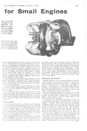
The turbine wheel is cast from heat-resisting alloy and, as in the compressor wheel, all blade sections are radial, thereby eliminating any bending stresses that might be caused by centrifugal force. The turbine housing is of the two-entry type, permitting separation and better utilization of the exhaust impulses from the engine.
SHAFT OIL SEALS The main function of the shaft oil seals is actually to limit the amount of air or gas leaking past them into the turbocharger-drain passages, and thence to the engine sump. where it would appear as additional blow-by. The piston-ring seal has been found to be particularly effective in this function: with suitable choice of materials it has also proved completely reliable even when operating under the high pressures associated with the use of an exhaust brake at the turbine outlet.
With the turbine-wheel alloy at present used, this design of turbocharger—having a wheel diameter of 4 in.—can operate continuously at speeds up to 68.000 r.p.m. and turbine inlet temperatures up to 760°C. (1,400°F.). This provides a pressure ratio of 2-5, a value which is more than sufficient for the vast majority of small turbocharged engines at present in production in Europe.
In the U.S.A., on the other hand, where the demand for higher engine mean effective pressures is greater, more highly rated versions of this turbocharger have been in production for about two years. These advanced models are of the same basic design, but use a nickel-base turbine-wheel alloy, in preference to the cobalt-base alloy of the examples illustrated on these pages.
The special requirements of automotive operation dictate the maximum possible response rate from the turbocharger, and this in turn implies the lowest possible moment of inertia of the rotating parts. To help in this the outer diameters of the wheel discs are deeply scalloped between the vanes. This feature also reduces centrifugal stresses in the wheel hubs and allows the use of higher tip speeds, or alternatively gives a higher— factor of safety at given turbocharger speeds and pressure ratios. It does, however, bring one undesirable feature from the designer's viewpoint, in that it gives him less control over the vibration patterns of the vanes, but this problem is now becoming well understood through the use of strain-gauging techniques.
a8 The major problem in high-speed. lightly-loaded plain bearings is overcoming oil-film instability. One simple method is to mount the bearing resiliently, and this can be simply achieved by using a fully floating bearing, as in the Holset turbochargers under discussion. The final development of this sire of bearing has shown no instability up to 146,000 r.p.m., which is the highest speed yet attained with the 4-in. wheel.
All current small turboblowers use oil tapped from the engine lubricating-oil circuit to lubricate their bearings. The alternative of a completely separate and independent oil supply, although superficially attractive from the turbocharger manufacturers' point of view, will undoubtedly give rise to immense servicing problems and would be a distinctly adverse selling feature. It has been found in practice that sufficient oil (about 3.5 pints per minute) can be tapped from the oil supply of most small engines without in any way affecting the pressure of the main engine circuit.
It is interesting to note that the turbocharger does not require finer filtration than is now becoming widely used for the main engine circuit itself: to be specific, filtration down to a particle size of 20 microns is now considered desirable for engine filtration, and small turbochargers are capable of giving many thousands of hours of service with this degree of filtration.
DAMAGE FROM FOREIGN MATTER The turbocharger is in a very vulnerable position on the engine, since there are many parts that can break off and pass through the turbine. These include injector tips, piece§ of valve and valve guide, pieces of piston, bits of gasket, and small pieces of metal flashing or core nails from the manifolds themselves. It would be possible to make the turbine wheel robust enough to digest many of these pieces, but this would make it so heavy as to be virtually unsuitable for automotive service. On the other hand, these problems do not occur in a fully developed engine, providing that it is used and maintained correctly, and it is now commonplace for the turbocharger to run uninspected through the major overhaul life of the engine.
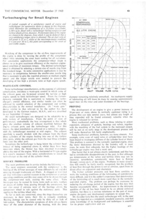
It has been Mr. Goodlet's experience that approximately 40 per cent of the problems with small turbochargers are caused by the passage of foreign matter through either the compressor or the turbine. Of the remainder, the majority are caused by faults in the lubricating oil supply. Inadequate air filtration, allowing excessive quantities of fine dust to pass through the turbocharger and engine, has been found to be more damaging to thc engine than to the turbocharger. Matching of the compressor to the air-flow requirements of the engine is done by varying the profile of the compressor wheel while retaining the same basic casting for all variations. For automotive applications the compressor-wheel shape is chosen so as to give maximum efficiency at the medium enginespeed condition of maximum torque. The desired turbocharger speed is obtained by selecting a certain size of nozzle ring from the standard range. In some automotive applications it may be necessary to compromise between the smaller-area nozzle ring that is necessary to give the required pressure at medium engine speeds and the larger nozzle area needed to prevent the developing of too high a pressure ratio at high engine speeds.
WASTE-GATE CONTROL
Some turbocharger manufacturers, at the expense of additional complication, introduce a waste-gate control in which some of the exhaust gases are by-passed around the turbine at high engine speeds to limit turbocharger speed. From the thermodynamic viewpoint this is equivalent to reducing the turbocharger's overall efficiency, and similar results can often be achieved by careful selection of the compressor and turbine characteristics in the normal installation. (A "waste gate' device similar to that referred to by the author has been developed by the German makers, MAN., and was described in our September 13 issue.)
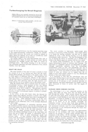
All small turbochargers are designed to be adaptable to a Wide variety of installations. From the point of view of performance, undoubtedly the best arrangement is that which gives the smallest volume of exhaust manifold between the engine exhaust ports and the turbocharger inlet. For this reason, the ideal installation is achieved on a vertical-six engine, with the turbocharger mounted at mid engine. The exhaust manifold is usually divided, with the exhaust from the front three cylinders of the engine feeding into one of the turbine inlet ports, whilst the exhaust gas from the rear three cylinders feeds into the other port.
Sometimes the turbocharger is hung below the cylinder head instead of being supported above it, whilst there have been occasions where the blower has been mounted transversely above the rear of the engine. With a horizontal or V-type engine it is usually necessary from space considerations to install the turbocharger at the end of the cylinder block.
SERVICE PROBLEMS The main problems met in service include the following: — The most common associated with the compressor is the fouling of the diffuser passages of vane diffusers by oil and dirt entering through inadequate air filters, A clogged or restrreted air filter will cause a partial vacuum in the compressor at certain opcating conditions and this may cause oil to be drawn through the compressor-end seals, causing the same effect. Vane breakages may be caused by loose items such as nuts, washers or pieces of rubber hose passing through the compressor, but can also occur if extreme wear of the bearings allows the compressor wheel to rub against the stationary parts. This applies to the turbine wheel also.
So far as seals are concerned, since the rings themselves are stationary in their bores, their life , is virtually indefinite. Rearing damage can be caused only by dirty oil or lack of lubrication. The characteristic symptoms of dirty oil are heavy wear of the outer diameter of the bearing, with the inner diameter remaining relatively unmarked. An inadequate supply of lubricating oil will leave its trace by causing approximately equal wear on the inner and outer diameters of the bearings.
PROVING
The development of an engine to give a power increase of 50 per cent or more above its normally aspirated rating is a process that can take several years. but almost any length of time expended will be found extremely valuable when the engine is released for service.
Most mechanical problems, such as those relating to piston expansion, adequacy of gaskets, bearings and valves, together with the matching of the fuel system to the increased output, will be met at an early stage in the development process and will make themselves felt fairly emphatically.
Some mechanical problems, however, are more obscure. For example, some cases of rapid valve or cylinder-liner wear have been traced to inadequate stiffness of the cylinder head or block. This problem is unusual in the normally aspirated engine, since the metal thicknesses dictated by the foundry will, in most cases, be more than adequate, but the higher loadings of the turbocharger engine may find a weak spot.
One factor that is not always clearly understood, and that has led to considerable disappointment in the past, is that although gas temperatures at the valves and turbine inlets may not be excessive, nevertheless considerably more heat is flowing through various part; of the engine. Problems in water circulation will usually be fairly readily recognized, but the problem of heat flow through the piston is not so obvious, apart from its direct effect on expansion and clearances.
The higher cylinder pressures and heat flows combine to make the working conditions of the lubricating oil considerably more difficult, and it is the author's experience that deterioration of the lubricating oil is much more rapid than in the normally aspirated engine. The problem can perhaps be overcome by reducing the oil-change period of the engine, but this may then become unacceptably short. An improvement in the detergent qualities of the oil has been found to be an almost universal solution, but there is a curious reluctance on the part of many engine des:alters and development engineers to accept this.
Mr. Goodlet feels that the small turbocharger will, in the near fUture, be regarded as a completely standard accessory, and that some knowledge of its background and techniques is essential for its proper application and use