


HOW WEIGHT DISTRIBUTION AFFECTS VEHICLE PERFORMANCE
Page 30
Page 31
If you've noticed an error in this article please click here to report it so we can fix it.
THE disposition of weight, both laden and Unladen, on the front and rear wheels of any vehicle has a definite effect on the all-round performance of the machine. This is particularly true of braking efficiency, but it also has its effect on other aspects, such as acceleration, steering and riding comfort.
It is a well-known fact that, in some of the more powerful private cars, it is possible for the tractive effort at the rear wheels to overcome road adhesion when the machine is started rapidly from rest and so cause the wheels momentarily to spin.
Once a vehicle is moving, its own acceleration redistributes the load, so that the weight on the rear axle is increased and further tendency to lose grip on the road is obviated. This redistribution of load, caused by acceleration, is an argument against the adoption of front-wheel drive, for, in this case, instead of the weight on the driving axle increasing when the machine is accelerating, it decreases.
Much of this starting difficulty, however, could be obviated by paying careful attention to weight distribution, although it must be admitted that there are conditions where the coefficient of friction between the tyre and the road is reduced to such a small figure that no amount of care in the distribution of weight would overcome wheelspia.
Effect of Weight Distribution on Steering
The effect of front and rear-axle weight on steering is, perhaps, not immediately obvious, but many operators may recall incidents where front-wheel adhesion was insufficient to permit of the machine being steered. The writer can recall one such occurrence when a prospective owner stated his own dimensions for a 30-cwt. truck. The machine had an exceptionally short wheelbase, in addition to which the purchaser insisted on normal control. Eventually the machine was completed, loaded, and sent out for test. The first slight hill encountered so affected the load distribution that the majority of the weight was transferred behind the rear &de, and the machine actually "sat up and begged." Such an occurrence is almost impossible with modern vehicles, but steering is affected by weight distribution, although, perhaps, not strictly by adhesion.
Imagine a lorry negotiating a bend at normal speed. Centrifugal force is assumed to act at the centre of gravity of the machine, and tends to push it away from the centre of the curve. Resistance to outward sliding is provided by the tyres in the same proportion as the loads imposed on them. Thus, if the weight distribution be 513/50, both front and rear tyres provide exactly the same resistance to skidding. If the weight distribution be twice as much on the rear axle as on the front, the resistance is as two is to one.
Weight distribution is governed by the longitudinal position of the centre of gravity, so that any centrifugal force, acting at the centre of gravity, would be distributed between the axies in the same proportion as the loads on the axles. Thus, in theory, action at the tyres is directly proportional to reaction, and, should skidding take place, it must do so with the vehicle broadsiding, with neither the the vehicle is actually under-steered if other contributing factors be ignored.
Creep is not wholly understood, but it is assumed by some engineers to be governed to an extent by the deflection of the tyre walls and treads. If a machine be fitted with single tyres at the front and twins at the rear, the deflection at the front will be greater than that at the rear, unless weight distribution be as one is to two. With all other combinations of axle loading, creep must take place at different rates at the front and rear of the vehicle, particularly with the more flexible low-pressure tyres.
A further effect of weight distribution on steering takes place through the springs. Orthodox semi-elliptic springs lengthen or shorten in effect, according to deflection, lf it be assumed that under normal loading conditions they are flat, then no matter whether they be induced into reverse camber by increasing the load, or allowed to regain part of their free camber by reducing the load, they become foreshortened.
Transference of the Load
Let us consider the ideal case where the springs are flat when the machine is fully loaded. On taking a bend some of the load is transferred to the outer wheels by centrifugal . force, the springs are put in reverse camber, and foreshortened by a specific amount. But the inner springs are relieved of the load, which has been transferred to those on the outside of the curve and are, therefore, allowed to regain camber, so that they become shorter by the same amount as the outer springs.
Thus, if the spring shackles be at the rear end of the springs, the axles move forward, because of the shortening of the springs, by the amount governed by the deflection, which is, in turn, controlled by weight distribution. So if the rear axle carries twice as much load as the front axle, the rear springs will shorten to a greater extent, and the wheelbase will be slightly decreased. With the same steering lock, a shorter wheelbase gives a narrower turning circle, and the vehicle is over-steered to a small degree.
Now, consider the case where the springs are not flat under load, but retain some of the original camber. Centrifugal force, caused by cornering, puts additional weight on the outer springs and makes them first become flat and then to go into reverse camber, the inner springs regaining more of their initial camber.
If it be assumed, for argument sake, that the outer springs become exactly flat under the additional load, it will be appreciated that they are then at their longest effective length, and the outer wheel of each axle is pushed backwards if the spring shackles be at the rear end of the spring. The inner springs, however, become shorter, and the inner wheels are pushed forward. Thus, the axles are Made to skew in the chassis.
As front and rear springs are never alike, as even with
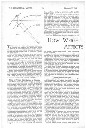
50-50 weight distribution they are made different so that periodicities shall not be identical, the amount of skew on each axle is different, and a condition similar to that shown exaggerated in Fig. 2, is induced. The off-side rear,spring is the longer and the axle, therefore, is shown more out of line so that slight over-steering occurs.
When the vehicle is designed; it is laid out for specific front and rear-axle loads, the springs being made to suit. In practice, the envisaged weight distribution is rarely achieved, and springs designed for a light load may be subjected to a heavy one and vice versa. When this occurs on a corner, axle skew can be so affected as to cause either underor over-steering. Commercial-vehicle drivers are fortunate in that the speed at which they travel is not sufficiently great for them to be unable to correct the misalignment by turning the steering wheel.
The greatest effect of weight distribution is on brakes, for it is on the static axle loading that dynamic, or moving, loadings depend, and it is primarily with dynamic loads that the brake designer is Concerned.
From Rear Axle to Front Axle When a vehicle decelerates, the load which is carried on the rear axle when the machine is stationary, is transferred to the front axle. As an example of this transference of weight, consider a light lorry of 3 tons gross weight, with a centre of gravity a quarter of the wheelbase length from the ground. If the machine be retarded with an efficiency of 100 per cent. (32.2 ft. per set. per sec.), the additional load transferred to the front axle is a quarter the gross weight, or 15 cwt. A normal static loading would be 1 ton on the front axle and 2 tons on the rear axle, so that dynamic loading becomes 1 ton 15 cwt. on the front axle and 1 ton 5 cwt. at the rear.
It is generally agreed that a vehicle of 3 ton& gross weight can be braked with 100 per cent, efficiency when fully loaded. The difficulties encountered by brake designers will be appreciated when the difference in axle loading, as mentioned, and the unladen weights are realized.
• Let us assume, for illustration purposes, that the load for she vehicle is 1 ton 15 cwt., and that unladen-weight distribution is the same as that for the laden machine, namely, as one is to two. Front-axle load for the unladen machine is approximately 8 cwt., and for the rear axle 16 cwt. Also, for illustration purposes, assume that the height of the centre of graVity is a quarter the wheelbase.
Weight transference to the front axle, with 100 per cent. retardation', is 81 cwt., which makes the dynamic loading, 161 cwt. on the front axle, and 7i cwt. on the rear axle. Thus, for identical retardation of the laden and unladen machine, there is a difference of 18i cwt. on the front axle and 17i cwt. on the rear axle.
The magnitude of braking effort on a wheel, if it is not to skid, is governed by the load carried by it. So, if the laden weight be taken as a basis upon which to work, it will be possible to skid the unladen machine with comparative ease. If, on the other hand, the unladen figures be adopted for braking calculations, the retardation of the laden machine will be considerably lower than the minimum required for safety. The commercial-vehicle designer is forced, therefore, to work entirely on laden figures, and trust to the skill of the driver to control his unladen machine.
The ratio of braking to be carried out by each axle should not exceed 60-40, that is, the front axle should bear a maximum of 60 per cent, of the braking.effort, and the rear axle 40 per cent. In order to conform with these figures, it is essential that weight distribution be given most careful consideration, for, as has been shown, the position of the centre of gravity of the laden machine is the deciding factor in determining the dynamic loads on the axles, and, hence, the amount of braking each can carry without skidding.
An examination of the figures quoted in the example for a loaded machine shows that, in this instance, braking ratio is 12-11, or about 58 per cent. on the front axle and 42 per cent, on the rear. With different static loading conditions, and a modified position for the centre of gravity, the maximum ratio of 60-40 could be greatly exceeded.
Suppose the static loading of the machine to be l tons on front and rear axles and the height of the centre of gravity to be 2/5ths of the wheelbase. Weight transference, for 100 per cent, braking, would be 2/5ths of the gross weight, namely, ti Eons to the front axle, and the dynamic loads would become 2.7 tons on the front wheels, and only 0.3 ton on the rear wheels. Whilst these figures appear ridiculous, it is, nevertheless, possible to obtain loading closely approximating to them.
Braking in this event is, of course, extremely difficult for the designer, for, if he allows the maximum 60-40 ratio, it in no way approaches that for the axle loadings, which is 90-10. If the braking effort cannot be made equal to resistance at the tyre, it is impossible to obtain the 100 per cent. retardation which is demanded for lighter machines.
Heavier machines cannot, except under extremely favourable conditions of tyre and road adhesion, be retarded with 100 per cent. efficiency, 60 per cent, being the figure usually aimed at. But these vehicles, in the same way as the lighter models, are still affected by weight distribution.
The vehicle designer is responsible, to a certain degree, for weight distribution, but he must assume, for his calculations, that the load is spread evenly along the whole of the body. If his estimates of braking performance are to be even nearly accurate, vehicle operators should co-operate and see that their machines are loaded as uniformly as possible, or braking must suffer. If the load be such that it can be evenly distributed, the matter is simple, but bulky, heavy loads, such as machine tools, etc., are not so easy to deal with. It is assumed by the designer that the centre of gravity of the body and load lies at the centre of the body, and all his calculations for brakes are based on this assumption. In order that the assumption can become fact, heavy-unit loads should always be placed in the middle of the body.