


A' COMPARTMENT TIPPING WAGON.
Page 30
If you've noticed an error in this article please click here to report it so we can fix it.
A Resume of Recently Published Patents.
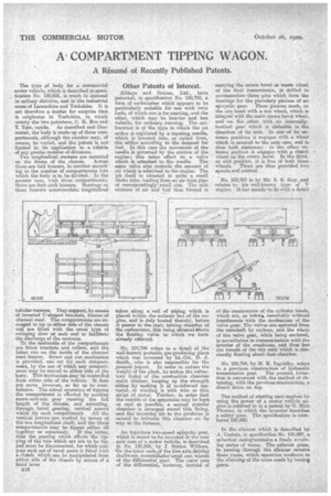
The type pf body for a commercial motor vehicle, which is described in speoi , fication No. 150,856, is much in demand in colliery districts, and in the industrial areas of Lancashire and Yorkshire. It is not therefore a Matter for surprise that it) originates in Yorkshire, in which county the two patentees, C. -IL Bee and T. Tate, reside. As described and illustrated, the body is made up of three compartments, although the number may, of course, be varied, and the patent is not limited in its application to a vehicle of any precise number of divisions. Two longitudinal runners are mounted on the frame of the chassis. Across these are laid bearers, in number according to the number of compartments into which the body is to be divided. In the present case, with three conipartments, there are four such beaters. Bearings on these beaters acoranmodate longitudinal
tubular runners. They support,. by means of inverted IT-shaped brackets, frames of channel steel. The compartments are arranged to tip to either side of the rho ssis and are fitted -with the usual type of swinging door at each end to facilitate the discharge of the contents.
To the 'underside of the compartments are fitted bracketsand rollers, and the latter ruir on the inside of the channel steel frames. Screw and nut meehanisni is provided, one set for each eompartment, by the use of which any compartment mar be moved to oithe,r side of the lorry. This mechanism ansy be controlled from either side of the vehicle. It does not move, however, so far as to overbalance. The actual operation of tipping the compartment is effected by another screw-and-nut gear running the full length of the chassis, and actuating.
• through bevel .gearing, vertical screws which tip each compartment All the vertical screws .are worked by means of the one longitudinal shaft, awl the three compartments, may be tipped either all together or separately. If the latter, then the gearing which effects the tipping of the two which are not to be tipped must be disconnected, for which put
pose each .se5 of bevel gears is fitted with a clutch. which can be manipulated from either side of the chassis by means of a
. hand lever • B18 "
Other Patents of Interest.
Alldays and Onions, Ltd., have patented, in specification No. 150,768, a form of carburetter which appears to be particularly suitable for use with twin fuels, of which one is for starting, and the other, which may be heavier ,a.,m1 leas vola,tile, for ordinary sunning. The carburetter is of the type in which the jet orifice is regulated by a tapering needle, which is lowered into, or raised from, the orifice according to the demand for fuel. In this case the movement of the needle is governed by the suction_ of the engine; this takes effect on a valve which is attached to the needle. The sasne valve also controLs the amount of air which is admitted to the engine. The jet itself is situated in quite a snail choke tube, leading Irons an air inlet pipe of correspondingly small size. The rich mixture a air and fuel thus formed is taken along a coil of piping which is placed within the exhaust box of the engine, and is duly heated thereby, before it passes to the main mixing chamber of the carburetter, this being situated *hove the floating valve to which we have already referred.
No. 150,796 refers to a detail of the well-known portable gas-producing plant which was invented by Lt.-Col. D.J. Smith, who is also responsible for the present patent. In order to reduce the weight of the plant, he makes the refractory lining of the combustion chamber much thinner, keeping up the -strength either by making it of re-inforced material, or winding it with wire or thin strips of metal. -Further, in order that the outside of the apparatus may be kept as O001 as possible a second annular chamber is arrange round this lining, and the incoming air to the producer is caused to triverise this chamber on its way to the furnace.
An ingenious two-speed epieyclic gear, which is meant to be mounted in the rear axle case of a meter vehicle, is described in No. 150,868, by J. Sutton Withers. On the -inner ends of the live axle driving shaftsare reounteCI4thef usual sun wheels of the differential gear. The outer ease of the differential, however, instead of
carrying the crown bevel or worm wheel of the final transmission, is drilled to accommodate three pins which form the bearings for the planetary pinions of an epieyclic gear. These pinions mesh, on the one hand with a sun wheel, which is integral with the main crown bevel wheel, and on the other with an internallytoothed gear which is shideable in the direction of its axis. In one of its extreme positions it engages with a wheel whioh is secured to the axle case, and is thus held stationary : in the other extreme position it engages with clutch wheel on the crown bevel. In the third, Or mid position, it is free of both these wheels. There are thus provided two speeds and neutral.
No. 150,767 is by Mr. S. S. Guy,,and relates to his well-known type of V &gine. It has mainly to do with a detail of the construction of the cylinder heads, which are as beforek, removable without interference with the mechanism of the valve gear. The valves are operated from the camshaft by rockers, and the whole of the valve gear, while being enclosed, is nevertheless in communication with the interior of the crankcase, and thus has the benefit of -the oily mist which is constantly floating alarait that chamber.
• No. 150,794, by M. K. Ingoldby, refers to a. previous, construction of hydraulic transmission gear. The present invention is concerned with the method of obtaining, With the previous construction, a direct drive on top.
The method of starting sere engines by using the power of a motor vehicle engine is referred to in a patent by G. Holt Thomas, in which the -inventor, describes a safety gear. The specification is numbered 150,840.
In the silencer which is descriBed by A. Castets, in specification No, 150,807, a spherical casings contains a freely revolving series of vanes. The exhaust gases, in -passing through the sfleareer revolve these vanes, which operation conduces to the silencing of the noise made by issuing gases.