


New Principle in Carburation
Page 36
If you've noticed an error in this article please click here to report it so we can fix it.
A Résumé of Patent Specifications That Have Recently Been Published
A CCORDINq to patent No. 556,205, 1—tit is impossible, with theordinary carburetter, to maintain a; constant airfuel ratio.owing to the• variation in air velocity as the piston descends on its
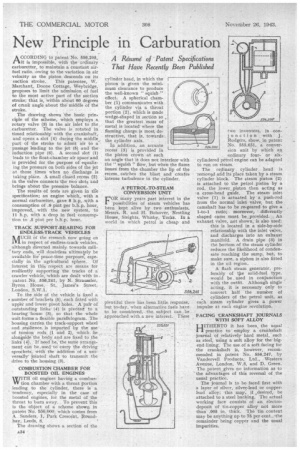
• suction stroke. This patentee, W. Marchant, Boone Cottage, Weybridge, proposes to limit the admission of fuel to the most active part of the suction stroke; that is, 'within about 60 degrees of crank angle about the middle of the stroke.
The drawing shows the basic prin, ciple of the scheme, which. employs a. rotary valve (3) in the air inlet to the carburetter. The valve is rotatedin timed relationship with the crankshaft,. and opens a slot (4) during the middle, part of the stroke to admit air to a passage leading to the jet (5) and the induction pipe (6). A second slot (1) leads to the float-chamber nit space and is provided for the purpose of equalizing the pressure on both sides. of the jet at those times when no discharge. is taking place. A small closed recess (2) in the valve connects the two slots add brings about the pressure balance. The results of tests are given in the specification; an engine 'which, with .a normal carburetter, gave 8 h.p. with a consumption of .9 pint per b.h.p. hour, improved, , with the new 'system, 'to 11 h.p. with a drop in fuel consumption to .5 pint per b.h.p. hour.
TRACK SUPPORT-BEARING FOR ENDLESS-TRACK VEHICLES
AUCH of the research now going on 1V1 in respect of endless-track vehicles,
although directed mainly towards mili tary ends, will doubtless ultimately be available for peace-time purposes, espe
cially in the agricultural sphere. Of interest •in this respect are means kr resiliently supporting the tracks Of a crawler vehicle, 'which are dealt with in patent No. .556,241, by N. Straussier, Byron. House; St. •James'.2 Street, London, S.W.1.
To the side of the vehicle is fixed a number of brackets (5), each fitted With upper and lower pivot holes. • A pair of outstanding links • (4) is pivoted to a bearing-house (3), so that the -whole unit. forms a flexible parallelogram. The housing carries the track-sppport wheel and resilience., is imparted by the use of torsion rods (1. and 2), which. lie alongside the body and are fixed to the links (4). If need be the same arrangement can be_used to' carry the driving sprockets, with the "addition of tit& versally jointed shaft to transmit the
drive to the housing (3). ,
COMBUSTION CHAMBER FOR BOOSTED OIL ENGINES WITH oil engines having a combusVV tion chamber with a throat portion leading to the cylinder, them is a tendency, especially in the case of boosted engines, for the metal of the throat to burn away.. To prevent this is the Object of a scheme shown in patent No, 556,000, which comes from A, Sa:nders, 1, Park CrescO4t, Round
hay, Leeds, S. " • The drawing shows a section of the a.34 cylinder head, in which the piston is given the minimum clearance to produce the well-known " squish " effect. A spherical chamber (1) communicates with the cylinder via a throat portion (2); which is made wedge-shaped in section so „ that the greatest mass of ; metal is located where the flaming charge is most de structive, that is, toWardSe the cylinder axis. .
In addition, an arcuate recess (3) is provided in the piston crown at such an angle that it does not interfere with • the" squish " flow, but when the flame issues from the chamber the lip of the • recess catches the blast an creates intense turbulence in the cylinder.
A-PETROL-,TO-STEAM CONVERSION UNIT FOR many years past interest in the possibilities of steam vehicles has been kept alive by two enthusiasts, Messrs. R. and H. Bolsover, Nestling House, Sleights, Whitby, Yorks. In a world in which petrol is cheap and
plentiful there has been little response, but to-day, when alternative fuels have to be considered, the subject can be approached with.a new interest. These two inventors, in conjunction with J. Rodgers, show, in patent No. 555,651, a conversion unit by which an ordinary fouror siccylindered petrol engine can be adapted to run on steam.
The ordinary cylinder head is removed and its place taken by a steam cylinder block. The steam piston (2) is attached to the petrol piston by a rod, the lower_ piston then acting as ,a cross-head guide. The steam inlet valve (1) is actuated by a push-rod from the normal inlet valve, but the camshaft has. to be re-geared to give a 1-to-1 ratio; moreover, differently shaped cams must be provided. . An exhaust valve, not shown, is also used;
this is located in a side-by-side relationship with the inlet valve, and discharges into an exhaust manifold. A drain pipe (3) in the bottom of the steam cylinder reduces the likelihood of condensate reaching the sump, but, to make sure, •a siphon is also fitted in the oil region..
A flash steam generator, preferably • of tp.e solid-fuel type, would be used in conjunction with the outfit. Although single acting, it is necessary only to convert half the number of
e cylinders of the petrol unit, as each steam cylinder gives a power impulse at each engine revolution.
FACING CRANKSHAFT JOURNALS WITH SOFT ALLOY
HITHERTO it has been, the usual practice to employ a crankshaft journal of relatively hard metal, such as steel, 'using a soft alloy for the bigend lining.The use of a soft facing for the crankshaft is, however, recommended in patent No. 556,247, by Vandervell Products,' Ltd., Western Avenue, London, W.3, and D. Green. The patent gives no information as to -• the advantages of this reversal of the usual practice.
The journal is to be faced first with a layer of silver, silver-lead or copperIced alloy: this may, if .clesired, be attached to a steel backing. The actual working face consists of an electrodeposit of tin-copper alloy not more than .005 in. thick. The tin content may be anything up to 7-5 per cent.,-the remainder being copper and the usual impurities.