


Workshop ways
Page 66
If you've noticed an error in this article please click here to report it so we can fix it.
THIS ARTICLE on ignition system fault diagnosis completes our series on 12V light vehicle electrics. It takes a look at how the basic system works and then gives the methods of tracing any faults. As before, the material has been prepared by the Technical Service Department of Joseph Lucas (Sales and Service) Ltd, who will be contributing to a similar Workshop Ways, but this time on 24V systems, due to appear in "CM" next month.
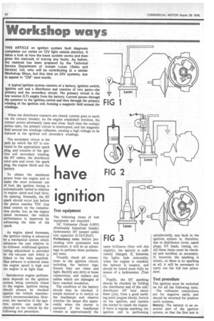
A typical ignition system consists of a battery, ignition switch, Ignition coil and a distributor and consists of two parts—the primary and the secondary circuit. The primary circuit is the low tension (LT) supply from the battery. Current passes through the ammeter to the ignition switch and then through the primary winding of the ignition coil, forming a magnetic field around the windings.
When the distributor contacts are closed, current goes to earth via the contact breaker. As the engine crankshaft revolves, the contact points alternately open and close. Each time the contact points open, the primary circuit is interrupted, and the magnetic field around the windings collapses, causing a high voltage to be induced in the ignition coil secondary windings.
The secondary circuit is the path by which the HT is conveyed to the appropriate spark plug, and consists of the ignition coil secondary winding, the HT cables, the distributor rotor arm and cover, the spark plug, the engine block and the battery.
To obtain the maximum power from the engine and to make the most economic use of fuel, the ignition timing is automatically varied in relation to engine .peed and load throttle opening. Normally, the HT spark should occur just before the piston reaches TDC (top dead centre) on the compression stroke, but, as the engine speed increases, the vehicle performance is improved by advancing the time of the spark.
As engine speed increases, the ignition timing is advanced by a mechanical system which advances the cam relative to its follower. Additional ignition timing adjustrhent is provided by the vacuum unit which is linked to the inlet manifold. Max advance is achieved when the engine speed is high and ale engine is at light load.
Satisfactory engine performance depends on the ignition system being correctly timed to the engine. Ignition timing should always be checked against the vehicle manufacturer's recommendations. However, the operation of the ignition system can easily be checked on the vehicle by the following test procedure.