


We have ignition
Page 66
Page 67
Page 68
If you've noticed an error in this article please click here to report it so we can fix it.
Test equipment
The following items of test equipment are required : DC Voltmeter (Scale 0-20V) (Preferably Industrial Grade); hydrometer; HT jumper cable; test capacitor (0.18-0.20J). Preliminary tests. Before proceeding with systematic test procedure, it will be an advantage to perform three preliminary tests.
Visually check all connections in the ignition circuit, including the battery lugs. Ensure they are clean and tight. Rectify any dirty or loose connections, and replace any cables which are damaged or have cracked insulation.
The condition of the battery should then be checked. A simple method is to switch on the headlamps and observe whether the lamps dim appreciably when the starter is operated. If the headlamps remain at approximately the
FIG 3
same brilliance (they will dim slightly), the battery is sufficiently charged. If, however, the lights fade noticeably, when the engine is cranked, the battery is suspect, and should be tested more fully by means of a hydrometer. (Test 1).
Finally, the HT sparking should be checked by holding the distributor end of the coil/ distributor HT lead about 6mm (in), from a good earthing point (engine block). Switch on the ignition, and operate the starter to crank the engine. If there is regular sparking, the ignition coil is performing satisfactorily, any fault in the ignition system is, therefore, due to distributor cover, spark plugs, HT leads, timing, etc. All these items must be checked and rectified, as necessary. If, however, the sparking is erratic, or there is no sparking at all, it will be necessary to carry out the full test procedure.
Test procedure
The ignition must be switched on for all the following tests.
The voltmeter connections are for negative earth, and should be reversed for positive earth systems.
Battery. The battery is an essential part of the ignition system, so that the first test is
FIG 4
to ensure that the battery is in a well-charged condition. Check that the battery connections are clean and tight. Then, use the hydrometer to determine the state of charge. All cell readings should be at least 1.230, indicating that the battery is at least 70 per cent charged. If the cell readings are lower than 1.230, the battery should be re-charged by means of a battery charger
FIG 5
(not, of course, a trickle charger).
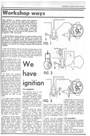
Checking primary circuit voltage at coil positive terminal. The next tests are to check the ignition primary circuit, that is, the LT supply line from the battery. First, we must check that there is -sufficient voltage at the ignition coil. Remove the distributor cover, and ensure that the contacts are closed, rotating the engine, if necessary. Then, connect the voltmeter between the ignition coil positive terminal and a good earthing point (for instance, the engine block or chassis). When the ignition is switched on, the voltmeter should indicate battery voltage, or 6V for ballasted ignition systems. (Fig 1).
If the voltmeter gives a zero reading the battery feed to and from the ignition switch should be checked, and also the appriate connections. Any faults should be rectified.
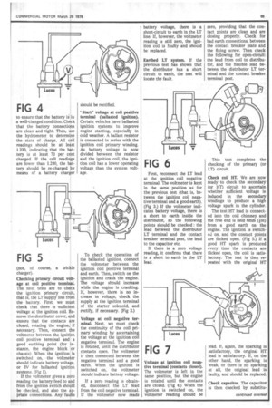
' Start ' voltage at coil positive terminal (ballasted ignition). Certain vehicles have ballasted ignition systems to improve engine starting, especially in cold weather. A ballast resistor is connected in series with the ignition coil primary winding. As battery voltage is now divided between the resistor and the ignition coil, the ignition coil has a lower operating voltage than the system voltage.
To check the operation of the ballasted ignition, connect the voltmeter between the ignition coil positive terminal and earth. Then, switch on the ignition and crank the engine. The voltage should increase while the engine is cranking, If, however, there is no increase in voltage, check the supply at the ignition terminal of the starter solenoid, and rectify, if necessary. (Fig 2.) Voltage at coil negative terminal. Next, we must check the continuity of the coil primary winding by ascertaining the voltage at the ignition coil negative terminal. The engine is rotated, until the distributor contacts open. The voltmeter iF then connected between the negative terminal and a good earth. When the ignition is switched on, the voltmeter should indicate battery voltage.
If a zero reading is obtained, disconnect the LT lead from the coil negative terminal. If the voltmeter now reads battery voltage, there is a short-circuit to earth in the LT line. If, however, the voltmeter reading is still zero, the ignition coil is faulty and should be replaced.
Earthed LT system. If the previous test has shown that the distributor has a short circuit to earth, the test will locate the fault,
FIG 6
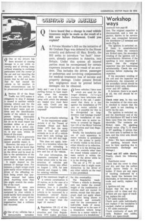
First, reconnect the LT lead at the ignition coil negative terminal. The voltmeter is kept in the same position as for the previous test (that is, between the ignition coil negative terminal and a good earth). (Fig 3.) If the voltmeter indicates battery voltage, there is a short to earth inside the distributor, so the following points should be checked : the lead between the distributor LT terminal and the contact breaker terminal post, the lead to the capacitor etc.
If there is a zero voltage reading, it confirms that there is a short to earth in the LT lead.
FIG 7
Voltage at ignition coil negative terminal (contacts closed). The voltmeter is left in the same position, but the engine is rotated until the contacts are closed. (Fig 4.) When the ignition is switched on, the voltmeter reading should be zero, providing that the contact points are clean and are closing properly. Check for bad earth connections, between the contact breaker plate and the fixing screw. Then check the following for open-circuit: the lead from coil to distributor, and the flexible lead between the distributor LT terminal and the contact breaker terminal post.
This test completes the checking of the primary (or LT) circuit.
Check coil HT. We are now ready to check the secondary (or HT) circuit to ascertain whether sufficient voltage is induced in the secondary windings to produce a high voltage spark in the cylinder.
The test HT lead is connected into the coil chimney and the free end is held 6irnm (tin) from a good earth on the engine. The ignition is switched on, and the contact points are flicked open. (Fig 5.) If a good FIT spark is produced every time the contacts are flicked open, the coil is satisfactory. The test is then repeated with the original HT lead. If, again, the sparking is satisfactory, the original HT lead is satisfactory. If, on the other hand, the sparking is weak, or there is no sparking at all, the original lead is faulty, and should be replaced.
Check capacitor. The capacitor is then checked by substitu tion, The original capacitor is disconnected, and a test capacitor, known to be serviceable was connected between the distributor LT terminal and earth (Fig 6).
The ignition is switched on. If there is unsatisfactory sparking, when the contacts are flicked open, the secondary winding of the ignition coil is unsatisfactory. However, if the sparking is now improved it shows that the original capacitor was not functioning satisfactorily. Check the connections before replacing the capacitor.
If the secondary winding of the coil and the capacitor are satisfactory, the remainder of the secondary circuit should be checked (rotor arm, distributor cover and HT cables).
If, however, there is no spark at all, the coil should be replaced.
Check rotor arm. In this test the insulation of the rotor arm is checked to ensure that the HT spark is not tracking to earth via the cam.
The ignition is switched on, and the distributor end of the coil/distributor HT lead is held 3mm (Ain) from the rotor arm electrode. The contacts are flicked open. No sparking should occur. (Fig 7.) If there is HT sparking, it proves that the rotor arm is earthed to the cam, and the rotor arm should be replaced.
(Note : We have emphasised HT sparking, because there may be faint sparking due to electrostatic discharge and leakage.) Visual and HT cable checks. Finally, check the following items : 1, Distributor cover Check that the cover is clean and dry, and that the carbon brush moves freely in its holder. If there are any signs of tracking (indicated by a thin, burnt line between two electrodes, or between an electrode and earth), replace the cover.
2, Ignition coil, top Ensure that the top of the ignition coil is clean and dry. If there are any signs of tracking, replace the coil.
3, HT cable insulation Check each cable individually, and replace if the insulation is cracked, chafed or perished. 4. HT cable continuity Check continuity of each HT cable. Replace any cables, which are open-circuit.