


The Latest Pneumatic Suspension System
Page 66
If you've noticed an error in this article please click here to report it so we can fix it.
THE well-known name of the Dunlop Rubber Co., Ltd., 32, dsnaburgh Street, London, N.W.1, appears in patent No. 429,963 describing, in conjunction with A. Healey, a pneumatic suspension system. The accompanying drawing shows one of several designs; in this case the road wheels are supported by bell-cranks connected to piston rods at each end of a common cylinder.
The piston itself may consist of an inflatable rubber bag (described in patent No. 320,633) connected to an air bottle in which pressure is maintained by a vehicle-driven pump. A control valve is located in the pipe line, so that the suspension may be adjusted to suit the load.
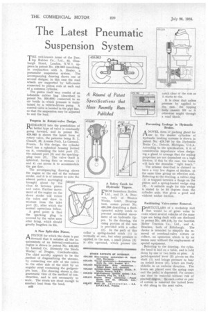
Progress in Rotary-valve Design.
RESEARCH into the possibilities of 1 ‘a better type of valve is constantly going forward, and in patent No. 429,983 is shown the latest form of rotary valve, the patentee being B. J. Chaude, 35, Avenue Foch, La Garenne, France. In this design, the cylinder head has a spherical housing formed on it, containing the inlet port (2), the exhaust port (5) and the sparkingplug bore (3). The valve itself is spherical, having flats or recesses (1 and 4) cut across it to accommodate. the gas flow.
The accompanying drawing shows the engine at the end of the exhaust stroke, and it is of interest to note the almost perfect scavenging brought about by the close fit between piston and valve. Further movement of the engine on the down stroke will rotate the valve and draw in mixture from the inlet port (2), after which the normal operations follow.
A good point is that the sparking plug is covered by the valve soon after firing, which should greatly lengthen its life.
A New Split-skirt Piston.
APISTON for which the claim is put forward that it satisfies all the requirements of an internal-combustion engine is shown in patent No. 430,052 by Limited Co. (formerly the Skoda Works)' of Prague, Czechoslovakia. The chief novelty appears to be the _method of diagonalizing the stresses, by connecting one side of the crown to the other side of the skirt by an angular strut containing the gudgeonpin boss. The drawing shows a diagrammatic view of the method of construction, and is not necessarily to scale. The struts are stout enough to conduct heat from the head.
s48 A Safety Catch for Hydraulic Tippers.
cROM Sunsaloon Bodies,
Ltd., and D. A. Pearson, both of Weston Works, Greet, Birmingham, comes patent No. 430,206 describing a fluidoperated safety catch to prevent accidental movement of an hydraulic tipper. In the drawing, the rising portion of the ram is provided with a collar (2). In the path of this collar a spring-loaded catch (1) is normally at rest, hut when pressure is applied to the ram, a small piston (3) is also operated, which presses the catch clear of the ram as it starts to rise.
It is clear that unless pressure be applied to the ram, the tipping body cannot lift. as it otherwise might through a road shock.
Preventing Leakage in Hydraulic Brakes.
ANOVEL form of packing gland for use in the master cylinders of hydraulic braking systems is shown in patent No; 429,749 by the Hydraulic Brake Co., Detroit, Michigan, U.S.A. According to the specification, it is of considerable importance when designing a gland to arrange that the sealing properties are not dependent on a high friction; if this be the case, the brake will lack the desirable " light touch."
The scheme described is claimed to have a very low degree of friction, at the same time giving an effective seal. Referring to the drawing, a rubber ring (1) is trapped between a flange on the piston and a spring-loaded wedge ring (2). A suitable angle for this wedge is stated to be 55 degrees from the cylinder axis; this gives a good seal without undue friction.
Facilitating Valve-cotter Removal.
PARTICULARS of a workshop tool that would be of great value in cases where several vehicles of the same type are being dealt with are disclosed in patent No. 430,118, by the Scottish Motor Traction Co., Ltd., and A. Bracken, both of Edinburgh. The device is intended to simplify the removal of overhead-valve cotters or collars, an operation which is by no means easy without the employment of special equipment.
Referring to the drawing, the cylinder head is laid on a table, and is held down by one or two bolts or pins. A pedal-operated lever (2) pivots on the shaft (1) and brings pressure to bear on forked levers (3), which are freely slidable in an endwise direction. The levers are placed over the spring cups and the pedal is depressed; the cotters can then be removed without risk of pinched fingers. As each cotter or pair of cotters is removed the forked lever is slid along to the next valve.