


SIDE TIPPING OF DEMOUNTABLE BODIES.
Page 62
If you've noticed an error in this article please click here to report it so we can fix it.
A R6sume of Recently Published Patent Specifications.
THE specification of J. S. Drewry and Shelvoke and Drewry, No. 272,805, describes a body which may be ecmposed of many separate containers, each of which, whilst being capable Of being tipped, may be rolled on and off the vehicle frame when desrecl, each container being mounted so
that it can be operated by a separate side-tipping device. Separate rails awe provided for rollers and a beam for the tipping, the container being held from rolling whilst tipping operations are in progress.
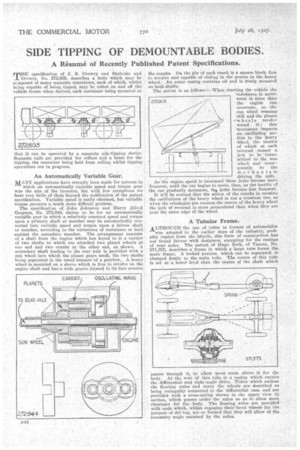
An Automatically Variable Gear.
MANY applications have recently been made for patents in
which an automatically variable speed and torque gear was the aim of the inventor, but with few exceptions we hear very little of them beyond the publication of the patent specification. Variable speed is easily obtained, but variable torque presents a much more difficult problem.
The specification of John. Johnston and Harry Alfred Grayson, No. 272,644, claims to be for an automatically variable gear in which a relatively constant speed and torque upon a primary shaft or member may be automatically converted into variable speed and torque upon a driven shaft or member, according to the variations of resistance or load against the secondary member. The arrangement consists of a shaft from the engine which has keyed to it a carrier of two shafts to which are attached two planet wheels at one end and two cranks at the other end, as shown. A secondary shaft leading to the rear axle is provided with a sun wheel into which the planet gears mesh, the two shafts being separated in the usual manner-of a gearbox. A heavy wheel is mounted on a sleeve which is free to revolve on the engine shaft and has a wide groove formed in its face nearest
the cranks. On the pin of each crank is a square block, free to revolve and capable of sliding in the groove in the heav-y wheel. An outer casing contains oil and is freely mounted on both shafts.
The action is as follows :---When starting the vehicle the resistance to movement is more than the engine can overcome, so the sun wheel remains still and the planet —w heels revolve round it; this movement imparts an 'oscillating motion to the heavy Wheel, the inertia of which at each reversal causes a jerk to be 'trans .. mitted to the sun wheel and consequently to the m.echanis'm driving the axle.
As the engine speed is increased these jerks become more frequent, until the car begins to move, then, as the inertia of the car gradually decreases, the jerks become less frequent. It wr'.1l be noticed that the action of the cranks in causing the oscillations of the heavy wheel is not a constant one, as wlen the crankpins are nearest the centre of the heavy wheel the jerk of reversal is more pronounced than when they are near the outer edge of the wheel.
A Tubular Frame.
ALTHOUGH the use of tubes in frames of automobiles was adopted in the earlier days of the industry, probably copied from the bicycle, this form of construction has not found favour with designers, excepting for the casings of rear axles. The patent of Hugo Reik, of Vienna, No. 271,375, describes a frame in which a large tube forms the main frame. A forked portion, Which can be separated, is clamped firmly to the main tube. The centre of this tube is set at' a lower level than the centre of the shaft which passes through it, to allow more room above it for the • body. At the rear of this tube is a casing which carries the differential -and right-angle drive. Tubes which enclose the floating axles and carry the wheels are described as being swingably. connected to the differential case and are provided with a cross-spring shown in the upper view in section, which passes under the axles so as. to allow more clearance for the body. The floating axles are provided with ends which, whilst engaging their bevel wheels for the purpose of drieing, are so formed that they will allow of the , necessary angle assumed by the axles.