


HYDRAULICALLY OPERATED BRAKES.
Page 13
If you've noticed an error in this article please click here to report it so we can fix it.
A System Which Might Well be Employed on Motor Coaches.
/a
A VERY interesting method of apply lug the brakes on all four wheels at the same time is employed on the new Duesenberg car, a vehicle of American design and manufacture.
We refer to this chiefly because there is no reason why a similar system should not be employed on commercial vehicles, and particularly on those used for the carrying of passengers.
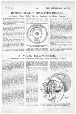
The -chief difficulty with four-wheel braking has been the transmission of the necessary motion to the elmee in the front wheel drums, but in the Duesenberg car this has been eliminated by adopting a hydraulic eyetern for brake operation. On the main cross-member at the middle of the chassis is a master cylinder, provided with the ordinary type of leather cup piston, and filled with oil. This cylinder is pivoted to the frame at its closed end, and the piston rod connects, through a link, with a frame bracket below the cylinder. From the pivot joint between thewistorr rod and the link a slime rod extends forward to
the brake pedal, the arrangement of this link mechanism being such that a toggle effect is produced when the brake pedal is depressed.
From the cylinder, oil-distributing pipes'extend to each wheel. These pipes consist ,partly of :seamless steel tubing
and partly of flexible tubing. These to the' rear brakes are carried along the diagonal brace node of the axle, and are thereby rendered inconspicuous; whilst at the same time they receiveeadequate support. The pipes to the. front wheel brakes are tarried for some distance along the frame side-members, and from thence the oil is conducted through the steering pivot by way of a central joint at the tap, to which it is led,by a bent piece of steel tubing and a fitting secured to the side of the steering knuckle. Using the steering pivots in this way eliminates the necessity for much exposed flexible tubing.
When pressure is applied, to the brake pedal, oil is forced from the master cylinder through the tubes to all four brake cylinders. As soon as the pressure on the brake pedal is released, the return springs withdraw the brake shoes from the drum.
Reference to the illustration accompanying this description will,show how the shoe-operating pistons are arranged. In addition to the hydraulic brakes, an emergency brake is mounted at the front end of the propeller shaft.