


Three Valves Per Cylinder
Page 36
If you've noticed an error in this article please click here to report it so we can fix it.
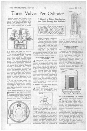
THREE valves per cylinder is the 1 chief novelty in a design of engine shown in patent No. 565,748, by A. Boorer, 120, Broadwater Street West, Broadwater, Worthing, Sussex. The third valve is a master, and its purpose is to protect the other two from the high combustion temperature.
The drawing shows how the master valve is centrally located, with the usual valves behind it. The master valve, when opened, descends almost to the level of the top position of the piston. The operating sequence is as follows: On the firing stroke, the master is, of course, closed, but opens near the bcatom of the stroke to release the exhaust. Meanwhile, the exhaust valve has been opened in readiness, so that a clear passage is provided. The master remains open during the next two strokes (exhaust and induction) while the other two valves function normally.The closure of the inlet stroke is, however, performed by the master, the inlet valve being closed later, By the use of this system, both the scavenging and the volumetric efficiency, it is claimed, are considerably improved, whilst cooling problems 'are simplified by the provision of ample water spaces around the seating of the master valve.
SIMPLIFIED HYDRAULIC BRAKE
PATENT No. 565,532 shows a design for an hydraulic brake, in which the expander motion is applied directly to the shoes without intervening links, levers or other parts. The patentee is
Bendix Aviation Corporation, South Bend, Indiana, U.S.A.
In the drawing, the hydraulic motor (1) has opposed pistons, one of which presses on the Upper shoe, whilst the other loads the lower one through The medium of an axle-clearing yoke (2). The shoes are anchored on a fixed pin (3) and an adjustable spreader (4); the latter is operated by a coned-head screw, which forces apart-a pair cif tappets.'
UNIVERSAL WHEEL FOR • TRACTORS • •
A TRACTOR wheel fitted With the i—.1-usual form of stoke cannot satisfactorily be bperated on the road unless some form of band he fitted. To avoid the need for this is the object of a wheel shown in patent No. 565,646. by 1-1, Elliott, Glen Firs, Bideford, Devon.
The drawing. shows the proposed wheel, which is fitted with V-shaped strakes formed in angle-iron. The invention consists of the attachment of tread pieces (1) made of rubber, hardwood, or other suitable material. These, whilst not reducing the grip on rough ground, present a substantially cylindrical surface to a road, and thus ensure. smooth travel.
A WHEEL FOR USE OVER ROUGH GROUND
AMUST unorthodox design for a wheel for cross-country work comes in patent No. 565,736., from G.
Jones, Keigwin Studio, Mousehole, Cornwall, who suggests .the use of a. rimless wheel fitted with flat, flexible, spring-steel spokes.
The drawing shows the action if the wheel when under load; illustrating the shape assumed by the springy spokes. The wheel also functions-as an automatic variable gear, heavy loading reducing the effective diameter and so lowering the gear. It also acts as a suspensiOn Syitina: this.. too.
accommodate itself to' variations of load, The success of the scheme would appear to depend mainly on the phyAce) properties of the steel used lor the spokes.
AN INJECTION.PUMP REFINEMENT
To reduce the side loading on the IL plungers of an injection pump 13 the main object of a modified design shown in -patent No. 565,136, by C.A.V., Ltd., and F. Evans, both of Warp/e Way; London, W.3. To this end, the ports are duplicated at diametrically opposite points, twp inlets (1) being. provided and a similar pair of spill orifices 121_ disposed at 90 degrees. The ports collaborate with ahelically grooved' plunger for regulating the output in the normal way.
ANinlet-air filter of the oil-wetted . type forms the subject of .patent No. 565,740, which comes from A. 'Goodloe, Montclair, New Jersey., U.S.A. The distinctive feature of the design is that.the filtering unit is in the farm of knitted wire mesh and when withdrawn for cleaning it maintains its shape, .
• Referring to the drawing, the incoming air•enters holes 1 and impinges upon the surfaCe of an.oil-bath (2). It then passes ;upwards through a cylinder (3) of knitted wire. leaves leaves via the exit at the top. Some of the oil • is tarried into the wire by the air
so that it is kept constant!): • Wei. The vhola cylinder, cars be engaged by a bayonet catch