


AN ANTI-FRICTION WORM DRIVE.
Page 76
If you've noticed an error in this article please click here to report it so we can fix it.
A Resume of Recently Published Patent Specifications.
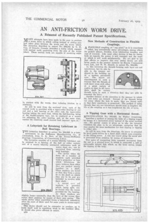
lUr ANY attempts have been made in the past to produce .iX1_ a worm drive in which rolling instead of sliding contact takes place between the worm and the worm wheel. The invention described in patent No. 304,541 by G. H. Guy, of Ontario, Canada, describes a worm which engages with conical teeth projecting from the side of the worm wheel. These conical teeth are capable of revolving while
in contact with the worm, thus reducing friction to a minimum.
As will be seen from the sectional view, each of the conical teeth is provided with a taper-roller bearing at one end and a ball bearing at the other end, the taper-roller bearing taking the main load, whilst the ball-bearing, being of the double-purpose type, can be employed as a means for adjusting the roller bearing, and, at the same time, carries the relatively Knell journal load imposed upon it. •
A Labyrinth for Retaining Lubricant in Ball Bearings.
THE invention described in patent No. 304,562 is a commuuication to the Hoffmann Manufacturing Co., of Chelmsford, from G. B.. Bott, of the Norma-Hoffmann Bearings Corporation, of Connecticut, U.S.A. • The invention consists of a means whereby lubricant can be retained in a bearing of the ball or roller variety, and of a means whereby unwanted substances such as water, dust, etc., can be prevented from entering such bearings.
The . device takes the form of a number of washers each provided with'-a projection or boss which determines the space between them when they are packed closely together • on a shaft. These washers are bored so that they form a press fit on the shaft on which they are to lie and me intended to revolve with their shaft.
A second set of washers is provided which, being split, can be forced into the recess provided for the bearing. As these washers are slightly larger externally than the bore of the recess, they retain their position by means of their own spring. The whole device whet assembled forms a labyrinth, something after the style of those used for some years in steam-engine practice.
This device should not be expensive to produce, as it lends itself well to repetition work in the machine shop. It should also prove efficient in action.
B50 .
New Methods of Construction in Flexible . Couplings. A FLEXIBLE coupling, or "rag joint," as it is sometimes called, has undoubtedly many advantages, among others its perfect silence, freedom. from 'lubrication troubles and ease of renewal. Like most other devices it has its limits, both as regards the power it will transmit and the angle at which it will work satisfactorily. We are glad to see that efforts to improve this very useful device are still being made, in the present instance by Morris Commercial Cars, Ltd., and W. W. Hamill, in patent lo. 304,395.
In this invention the threads forming each layer -are not interwoven, but lie side by side in the manner employed in the building up of a modern pneumatic tyre. The layers are superimposed in such a manner that the threads of each layer cross each other at a great variety of angles, so that, in all eases, there shall be certain threads lying in such a direction that they are able to transmit the drive.
Another feature of the invention is the manner in which the bolt holes are formed. Instead of the threads being cut away where the hole is made, they are forced aside so that their continuity is preserved. The method cf using threads that are not interwoven should tend to lengthen the life of the coupling as it has lengthened the life of tyres.
A Tipping Gear with a Horizontal Screw.
SPECIFICATION No. 303,655, by Walter Armstrong, describes a method of raising the body of a tipping wagon by means of a horizontal screw instead of the usual vertical one. No special reason is given as to why the inventor considers his plan to be an advantage, excepting that he may employ the same mechanism for rear tipping or tipping to either side.
As will be seen from the drawings, the screw is actuated by bevel gears driven by a hand shaft which runs crosswise to the lifting screw. A nut -can 'travel along thd sereW and is prevented from rotation by means of trunnions.
Two pairs of connecting links transmit movement from the nut to a pivoted lever, to which is connecttd a ball or universally jointed link which, as the lever moves, causes the tipping of the body.