


Primrose Improve Third-axle Suspension
Page 57
If you've noticed an error in this article please click here to report it so we can fix it.
As announced in last week's issue, the Primrose Third Axle Co., Ltd., Clitheroe, Lancs, have developed a new form of suspension for third-axle conversion. Hydraulic compensation is used to reduce the tendency for either of the axles to hop when braking, and the layout makes use of four identical semielliptic springs. Components are easy to apply to existing chassis.
The new suspension is known as the H4 type, and is applicable to all the types of . vehicle currently being converted into six-wheelers by this company, whilst it can also be applied to tandem-axle semitrailers.
It has the advantage over the coil-spring type of conversion system used by the Primrose concern in that higher loading can be applied to the trailing axle. The arrangement of the coil-spring layout was not acceptable to some operators, whereas the new version—with its conventional springs—should meet with more approval. The coil-suspension conversion is to remain in production.
Loadings Increased
Because of the greater loading which the new bogie can withstand, the H4 suspension design can be applied to 14-ton-gross four-wheelers to convert them to 20-ton-gross vehicles. The layout provides for better load distribution between the driving and trailing axles, and a special valve introduced between the hydraulic cylinders on each side of the chassis ensures relatively smooth riding when in unladen condition.
The new design was made primarily as a result of certain operators' unacceptance of the elliptical-coil-spring layout. As a result of this reaction, a four-spring suspension system was considered, but the conventional balance-beam layout was discarded in view of its disadvantages under severe braking conditions.
Alternative forms of mechanical linkage were also considered and rejected, and eventually--partly as a result of earlier experiments with hydraulic-compensation systems—a Guy Warrior four-wheeler was converted to an eight-wheeler about 15 months ago, and the rear bogie had the prototype of the new suspension. Only minor design modifications were necessary before the system reached its final form, and the prototype was found to be entirely satisfactory.
The springs used in the conversion are all identical and not the same as the rear springs of the original four-wheeler being converted. The springs are attached at their forward ends to conventional hanger brackets, all four of which are identical, whilst the rear ends of the springs have no eyes. Instead, the three upper leaves remain straight and are sheared off to the same length.
These rear ends abut against the spherical ends of piston rods which are integral parts of the four hydraulic pistons. Specially formed slipper brackets ensure that the spring ends do not lose contact with the ends of the piston rods. These slipper brackets permit free movement of the springs in a longitudinal direction.
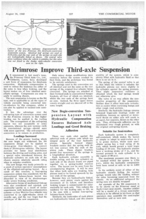
Each hydraulic cylinder assembly is double acting, and the two cylinders on each side of the chassis frame are piped together via a spring-loaded reaction valve. The layout can be seen from the accompanying diagram. It will be seen that when both axles are braking, both pistons tend to be forced upwards by the rear ends of the springs.
Because they are hydraulically linked. however, each piston reacts against the movement of its fellow, and therefore braking torque is compensated for automatically by each axle. This reduces the tendency for the leading axle to lift, as is the case with a normal four-springbalance-beam layout.
Similarly, the undersides of each piston arc hydraulically linked, and this ensures stability of the system, which is completely filled with hydraulic fluid so that there is no air in it.
The spring of the central valve is set so that when the vehicle is unladen the hydraulic pistons can move slightly in the cylinders against the spring pressure. Thus slight suspension resilience is obtained which the leaf springs would not otherwise give.
The valve in no way affects the nonreactive properties of the suspension. Neither does it affect inter-axle articulation as occurs when traversing bumps and other rough road sections.
Similarly, the hydraulic linkage ensures balanced bogie-axle loadings under all conditions, because an upward or downward thrust on either axle will result in an equal, but opposite, thrust on the other axle. Thus, driving-axle adhesion can be maintained over rough ground, as with the original coil-spring layout.
Suitable for Semi-trailers
Each hydraulic system is completely self-contained, which makes the layout as simple to adapt to semi-trailers as it is to prime movers, whilst each semielliptic spring has a load rating of 41 tons, which would permit a total bogie loading of 18 tons. The hydraulic pistons have a working stroke of 5 in., and the normal pressure in each cylinder is in the region of 80 p.s.i.
The maximum pressure ever likely to be reached within the system is 1,750 p.s.i., whilst the hydraulic components have been tested as safe at up to 2,000 p.s.i.
In the unlikely event of either of the hydraulic circuits failing, the normal springs would take the loading without the axles becoming separated from the chassis. As an additional safeguard the spring eyes are double wrapped.
An exarnple of the H4 suspension is to be shown on the Primrose stand at Earls Court next month. Another exhibit will be a model of a 12-ton semi-trailer which is to be offered in kit form so that operators may assemble the semi-trailer themselves and so save cost.