


A Clutch for Use Behind the Gearbox
Page 66
If you've noticed an error in this article please click here to report it so we can fix it.
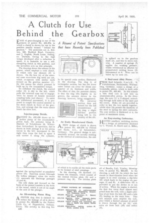
A R6urne. of Patent Specifications that have Recently been Published EASE of gear-changing is one of the objects of patent No. 425,374, in which a clutch is shown for use in the position usually termed " behind the gearbox." The patentees are A. Bolton, 182, Radford Road, Coventry, and J. English, North Learn, Felling, co. Durham. Owing to the high torque developed after a reduction in speed, it is desirable to use a selfenergizing clutch in this position, and the invention acts on this principle.
The drawing shows the essence of the patent, which employs a cone clutch, of which only one element (3) is shown. On the face (4) of the external cone wave-form dog teeth are cut, which co-operate with similar teeth formed on the gearbox member (1) . By this means the clutch pressure is built up by the transmitted torque.
To withdraw the clutch, the control collar (2) is slid to the left, which pulls the external cone out of engagement by means of loosely mounted coupling bolts (not shown). To assist the withdrawal movement, it is proposed to couple the control member to the main clutch in front of the gearbox, and arrange that the main clutch break the drive first.
Injection-pump Details.
DATENT No. 425,430 shows an in
jection pump of the accumulatorpiston type, the patentee being B. Bischof, of Tobelstrasse 16, Winterthur, Switzerland. In operation, fuel is drawn in from passage 2 as the piston moves to the left; movement to the right then traps the fuel in space 4 and carries it along the cylinder, against the spring-loaded accumulator piston (3). Injection occurs (through the hollow plunger) when the recess ' (1) uncovers the discharge passages (5 and 6).
The sole claim put forward as the basis of the patent consists in the form of the recess, which is cut at an angle to the axis of the plunger.
An Oil-retaining Piston Ring.
PA.A PISTON ring that is claimed to reduce the leakage of oil is shown in patent No. 424,646 by the Perfect Circle Co., of Hagerstown, Indiana, U.S.A. The novelty in this ring lies
B48 in its special cross section, illustrated in the drawing. The ring is of 'rectangular section, but has the lower outer corner cut away for about onequarter of its thickness and width. The effect of this, the patentee claims, is that the ring tilts slightly in its groove, the amount shown in the drawing, however, being exaggerated.
The cut-away portion does not extend for the full circumference of the ring, a slight full-face portion being left in the vicinity of-the slit.
An Easily Manufactured clutch.
ANEW design of clutch is shown patent No. 425,276 by Fichtel and Sachs, A.G., of Schweinfurt, Germany. The general design is substantially normal, the novelty residing in the method of construction, the aim
of which is to enable all the main parts to be formed of steel pressings.
In the drawing, the flywheel (1) houses the elements, which consist of the central friction plate (3) and a pressure ring (8). The friction plate
is splined on to the gearbox shaft (2) , and free to move endwise. A number of springs (7) applies the working pressure,: whilst withdrawal is effected by pressed-steel rocking levers (5) fukrummed at 6. Wear can be taken up by nuts (4).
A Steel-cored Alloy Piston.
FROM Karl Schmidt, G.m.b.H., '0, Fabrikstrasse, Neckarsulm, Wiirtemberg, Germany, comes a design of a bi-metallic piston, which is dealt with in patent No. 425,461. In this scheme a thin steel core is cast into an aluminium-alloy piston. In the drawings, the core (1) is U-shaped, extending through both sides of the skirt and the crown. Holes (2) are provided in order to key the two metals together, whilst slots (3). permit the elasticity of the steel to spring the skirt outwards. The core section is thickened at 4, the point of maximum stress.
An Easy-starting Carburetter.
HAVING auxiliary enriching devices is a design of carburetter disclosed by C. Wynne, E. Knott and A. Miller,