


Control Valve for Suction operated Trailer Brakes
Page 54
If you've noticed an error in this article please click here to report it so we can fix it.
FROMthe Clayton Dewandre Co., Ltd., and J. Rodway, both of Titanic Works, Lincoln, comes, in patent No. 578,314, an improved type. of vacuum control-valve for use with servo-brakes on trailers. The aim of the scheme is to give the driver an accurate 'feel,' so that he can gauge exactly the braking. effect he is applying to the trailer.
The unit (1) is intended to be interposed in the pull-..rod between the pedal and the brakes of the tractor. The suction supply is connected to a port (2), whilst a second port (3) is piped to the brakes on the trailer. Suction is applied to the trailer brakes when the valve. (4) is lifted from its seating, as shown by movement of the plunger (5).
When the valve is open, the suction also affects a piston (6), which tries to close it again. The closing force is transmitted to the pedal via a doublereaction lever (7); this can, by means of lost-motion links, vary slightly the length of the pedal-rod member, and so convey the force to the driver. If suction should fail, the pedal would continue to operate the tractor brakes, with only a small amount of lost motion.
TORSIONAL VIBRATION DAMPER
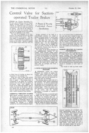
TO absorb torsional vibrations generated in, say, a crankshaft, is the aim of a damping device shown in patent No. 578,198, by Fairbanks, Morse and Co., Chicago, Illinois, U.S.A. Designed originally for aircraft, it is equally suitable for any multi-cylindered engine.
Firmly attached to the shaft is a triple-flanged member (I), which is bored at several points to receive pins (2). Hardened bushes are employed about the pins, but they are much larger than the pins and permit considerable play. In the intermediate spaces are housed sets of weights (3); these are freely movable in an in-andout direction, because they, too, are a slack fit around the pins.
The action of the device depends on the pendulum-like motion of the weights, which absorbs sudden pulses of energy as are produced by vibrations. A feature of the scheme is that the pins may have two diameters, as shown; by this Means the frequency-response of the device is widened. An important point is that of lubricatiOn, and for this purpose the whole unit is amply supplied with oil passages fed from a pressure supply.
A NOVEL SCHEME FOR STEERING TRAILERS
ASTEER1NCi system for trailers forms the subject of patent No. 578,281, which comes from R. Collis, "Glenwood," Union, Ontario, Canada. The claims made are for increased stability and ease in reversing.
The drawing shows a plan view of a four-wheeled trailer chassis embodying the invention. it will be noticed that the drawbar (1) is not pivoted in a horizontal plane, but is provided only with a vertical hinge. When the tractor corners, therefore, it exerts a sideways push on the trailer, and the steering mechanism is arranged to respond to this stimulus.
A pair of stub-axles is mounted upon a single axle (2), which is attached to the frame by swinging links (3). A lateral thrust thus causes the whole axle to move across the frame, and this is converted into steering action by the tierods (4), which are fixed to the frame.
The rear axle is similarly constructed, but, as no lateral force is generated at this end, the axle is made to copy the motion of the front one by means of coupled hydraulic cylinders. If a fixed middle axle be provided, however (malç.. ing the vehicle a six-wheeler), the rear axle will automatically copy the front one, because the frame would act as a lever, the middle axle functioning as the fulcrum.
MODERN PRACTICE IN CASTING CRANKSHAFTS
PATENT No. 578,373 comes from the Ford Motor Co., Ltd., 88, Regent Street, London, W.1, and discloses details of moulds for casting multi-cylinder crankshafts. Whilst it I comparatively simple to cast, say, a four-cylinder shaft, many problems arise as the number of journals increases, and the present scheme is intended to solve some of them.
The mould is built up from super imposed segments (1) of baked coresand, appropriately cored to suit the outline required. Each piece is provided with a semi-circular registry notch, which is pressed into contact with a round pillar (2), to ensure alignment of the whole. When the assembly is complete, damping rings (3) are placed over, as required, to convert the stack into a rigid whole. Two shafts are cast at once, the central runner (4) serving to feed the bottom end of each shaft.