


Oil-cooling for Crankshaft Bearings
Page 54
If you've noticed an error in this article please click here to report it so we can fix it.
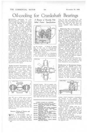
INTENDED principally for compression-ignition engines, a crankshaft cooling system forms the subject of patent No. 493,660, by F. Tippen, 3, Eastleigh Avenue, Earlsdon, Coventry. This inventor states that the usual lubrication system forms a valuable means for heat dissipation, and he proposes to amplify this by the circillation of oil in excess of the quantity required for lubrication.
The drawing shows a section of the central main bearing of an engine, and this is typical of the rest of the bearings, including the big-ends. Oil from a gear pump arrives at the port (3) and passes, via a passage (2), down into a conduit (5), which leads to all the main bearings. Each main bearing takes its supply through a hollow bolt (8) leading to circumferential passages (1) around the outside of the bearing shells. From this point the oil returns to the sump, via a restricted bore (4).
It should be understood that these arrangements constitute an oil circuit additional to the normal lubrication system, and the pump is designed to supply the extra quantity required. The supply to the pump is carried along a passage 6 which is surrounded by a water jacket (7) connected to the cooling system of-the engine.
Rubber-mounted Transmission Joint.
CROM that specialist concern, Hardy Spicer and Co., Ltd., and T. Waldron. both of Birch Road, Witton, Birmingham, comes patent No. 493,794, describing a design of transmission coupling in which a rubber ring acts as a resilient member. The drawing shows a section of the coupling, which comprises a pair of driving pins (2) and a similar pair of driven pins. Each pin is fitted with a grooved ball (3) made of metal and the four balls are embedded in a rubber ring (1) which unites the assembly. A two-part sheet-metal casing (4) surrounds the rubber ring, and is held together by bolts spaced between the ball portions.
Selective Timing of Tractor and Trailer Brakes.
WHEN a tractor-trailer outfit is VV braked it is necessary, if overrunning is to be prevented, that the trailer brakes be applied a little earlier, or somewhat more forcibly, than those on the tractor. A device to ensure this, in the case of fluid-operated brakes, is described in patent No. 493,330, by Robert Bosch G.m.b.H., of Stuttgart, Germany..
The device consists of a distributor valve, and is shown in the drawing in a form suitable for compressed-air operated brakes. The air supply, controlled by the driver's pedal, arrives at the valve via pipe 3. Pipe 1 leads to the tractor brakes, whilst those on the trailer are supplied from pipe 2. In operation, air arriving via pipe 3 passes, unhindered, into the trailer pipe through ports in the valve body. So soon as the pressure has risen to a certain value the ball valve (4) is forced from its seat, and passes air, via passage 5, into the tractor-brake pipeline. The other ball valve (6) is to permit the return of air from the tractor cylinder when braking has ceased.
Eliminating Wear of Crankshaft.
THE crankshaft of an engine is a most expensive unit to replace, and designers have therefore aimed at keeping wear down to a minimum, usually by the use of co-operating white-metal alloys. A scheme in which the journals are relieved of wear is disclosed in patent No. 493,581, by General Motors Corporation, Detroit, Mich., U.S.A.
This patentee proposes to apply the anti-friction facing to the surface of the crankshaft journals, instead of in the big-ends and main bearings, as heretofore. A thin steel shell, split for assembly, surrounds each journal and the exterior of these shells is faced with lead-bronze. To key the shell to its journal, a single dowel-pin is used in each case; this being sufficient support to the halves of the shell.
The connecting rods and main bearings are fitted with hardened steel bushes; in the case of the big-ends the bores themselves can be hardened.
Modifications in Ricardo-head Design. DATENT No. 493,702 comes from 1 that well-known specialist in oilengine combustion systems, H. R. Ricardo, 21, Suffolk Street, London, S.W.1, and discloses his latest sugges
tions in this field of research. The invention consists of slight modifications to the shape of the combustion chamber of this inventor's existing system, which comprises a hemisphere (1) located in the cylinder head mating with a second hemisphere (3) formed in a screwed-in plug, the volume of the space thus created being not more than 50 per cent, of the total compression space.
The improved design calls for a departure from the true spherical chamber ; this is modified into a cylinder with a hemispherical end, the extent of the parallel po,rtion being small, actually about .15 in., as indicated at 2 in the drawing.
The direction of length increase is in the line of injection, and it is said to minimize the risk of fuel striking the opposite wall.