


A Convertible Endless-track Vehicle
Page 60
If you've noticed an error in this article please click here to report it so we can fix it.
A Résumé of Recently Published Patent Specifications
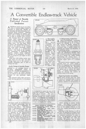
AVEHICLE which may be run either with or without endless tracks, is described in patent No. 479,814, by N. Straussler and Alvis-Straussler, Ltd., Holyhead Road, Coventry. Although designed presumably for military purposes, such a vehicle would doubtless be of value in roadless areas overseas.
The drawing shows the suspension system, which comprises spring-supported rocking bars, each of which carries a driving wheel and a smaller rolling wheel. All tour large wheels are driven, the transmission being contained in the interior of the rocking bars, from which universally jointed shafts are taken to a double-ended gearbox. • The whole of the transmission mechanism is duplicated, two separate engines being employed, although, in an emergency, it is pos-. sible to arrange for one engine to drive all wheels.
When used with endless tracks, each engine drives its own side, but when running direct en to the ground, a common ' differential gear is used to balance the load; .
Precise Timi_sig of Injection Pumps.
• .
.1:ROM _s. A. Adolphe Saurer, of 1Arbon, Switzerland, comes,. in patent No. 479,162, an arrangement, of governor control by which injection can be altered to the most favourable moment for any particular engine speed_
The patentee states that governors, whilst moving generally in accordance with engine speed, do not always do so in a. constant relationship, and the patent deals with a mechanism for correcting this defect. The drawing shows a fluid-operated governor (3) which rocks a cam-plate (2), the tatter, in turn, operating a bell-crank (1) attached to the advance-retard control of the pump. Whatever may be the characteristic of the governor, by suitably forming the contour of the cam (2) the pump timing can be corrected to that found most favourable for_ the. particular engine speed.
A34 A Non-aooting Sparking Plug.
T0 prevent sooting a n d preignition are the objects of a design of sparking plug described in patent No. 478,929, by M. Delattre, SainteGenevieve, Oise, France, w h o states that such faults can readily be prevented if the central insulator be a d equately cooled. To achieve this,
it is proposed to equip the nose of the plug with a chamber, within which the spark gap is located. The nose is pierced with a number of holes directed upwards towards, the central insulator sleeve. It is claimed that, during the compression stroke, the jets of mixture from the holes impinge on the insulator at once scavenging and cooling. A Self-governing Carburetter.
A SELF-GOVERNING carburetter "—V modification forms the subject of .patent No. 479,633, by S. A. Solex„ 190, Avenue de Neuilly,
Seine, France. The improvements are concerned with a remote control for adjusting the tension and flexibility of the operating spring.
The drawing shows a carburetter in which the unbalanced throttle valve
(4) is bias opening towards the openg position by a spring (2). engine suction representing the closing force. A balance is thus reached, which tends to maintain engine speed at a constant value.
The remote control comprises a cableoperated lever (1) which carries a pinion (5) engaging xvith a rack formed on the spring housing (3). Movement of the lever thus varies the tension of the spring and so adjusts the engine speed. A further improvement is a means for altering the number of effective turns of the spring.
Improving Gearbox Accessibility. .
THE latest novelty from the Tatra concern of Czechoslovakia is shown in patent No. 479,805, and consists of a gearbox suitable for incorporation in
a vehicle having a central tubular chassis. The object is to house. the gearbox in an accessible position in the front of the vehicle without, at the same time, unduly increasing the front overhang.
Referring to the drawing, it. will be seen how the gearbox is arranged about a vertical axis, with the input and output members constituted by pairs of bevels. By this means, not only is the assembly kept short, but, when dismantling, the gearbox may be lifted without disturbing the adjoining shafts.