


WORKSHOP GAUGES.
Page 27
If you've noticed an error in this article please click here to report it so we can fix it.
Simple and Useful Accessories Made by Our Driver and Mechanic Readers.
ONE OF the most important. items in the equipment of any engineering factory or workshop is that of gauges. Not even the little repair shop can exist without them; that is to say, it cannot so exist if it would have any claim at all to efficiency. In the case of a motorcar factory, the expenditure on gauges may he large indeed : its equipment is also very comprehensive, comprising, on the one hand; expensive micrometer gauges and similar appliances capable of measuring accurately to within very fine limit, as well as gauges and,jigs of all kinds for use when manufacturing the various component parts of the ears which the factory tarns out. Then there are the more or less approximate gauges designed to facilitate assembly and erection of those parts when completed. In genenal, the uses of gauges are two-fold. They are employed to ensure accuracy in manufacture and also to facilitate and ex.pedite the various operations which have to be carried out. in the process of znakin.g any important piece of mechinery.
In many cases these gauges have been made by the mechanics themselves, in order to enable them more readily to cope with the work which they have to do, and the following hints, regarding
the construction of such devices, are sure to be of use to the many readers cd this page who, whilst engaged upon the same class of work, have not hitherto discovered for them selves the special means of making their work. easier and ensuring its efficiency.
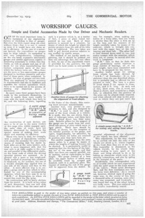
Those who have to deal, for example with a number of chain-driven vehicles will admit the necessity for some simple means of ensuring that the chains on both sides are at the same tension, and, what is more important still, that the rear axle is at right angles to the chassis and parallel to the differential shafts, on the outer ends of which the driving sprocket pinions are mounted. As a general rule a more or less rough-andready method of :ensuring this condition is employed, as, for instance, the use of a wooden straight-edge applied first to one side of the chassis and then to the other. A more efficient way is to employ a gauge such as that which is illustrated by one of the accompanying sketches, which has been sent to us by "M.M.," of Kensington, to whom we award this week the 15s. prize.
Its construction will be fairly obvious from the sketch. It is built of two tubes of such dimensions that one will slide within the other. Near the outer end of
each is a pointer which is, as a matter of fact, a piece of plain round bar pointed at one end. Each of these pointers is Secured by a setscrew, by means of which the length by which the pointer projects from the side of its tube may be regulated. The two tubes are held in any desired position relative to one another by similar means.
The method of use hardly needs explaining, but it should be pointed out that one advantage that this tool offers is that, by use of the adjustment which is provided for the pointers, the bar itself can be held (while in use) parallel
trythe frame of the chassis, thus ensuring more accurate measurements.
Another toel, very similar in construction to this, and also designed by "M.M.," is used to check the alignment of the front wheels of a vehicle. It is made, like the one above, from a pair of telescopic tubes, arid these have pointers fitted direct into their outer ends. Suitable pillars for the support of the gauge can be made from bar steel, fitted into pieces of plate which serve as lose plates. These bars should be &tilled, as shown, for the reception of the tubular portions a the gauge, and again, longitudinally, for setscrews, by means of which the tubes are retained in position once they have been set.
Yet another suggestion from the same source refers to a gauge by means of which the lengths cif beating brasses can he checked. It is particularly useful in ensuring that the two halves of the bearing are of the same length,. and that their two faces are exactly parallel, one to another, and-rat right-angles to their length. The-gauge consists of a base plate, the upper surface of which must be . carefully trued up, scraped and finished, until it is perfectly plain. The manner of making the rest of the gauge will be apparent from the sketch. In use, for example, when making the halves of a brass alike, that one which is shorter than the other is first set up on the base and the measure of its length carefully taken by means of the setscrew, which is brought into contact with the upper lace of the half hearing and there left. The other half is then dressed down until it, toe, just makes contact with the setscrew, which must not, of 00111.50, be moved until the work is completed.
"M.M." tells us that he finds this gauge particularly useful wherever a large number of bearings, all of the same length, have been reinstalled and have to be prepared for the turner. Another useful gauge for setting front wheels has been devised by " A.S.B.," of Colchester. It is less elaborate than the one described above, but is probably just as efficient for the purpose in view. The base is a piece of woo.d about 2 ins. square in cross-section, and 5 ft. long. At each end of this, short arms, also of wood, a-re fitted as shown, each secured by a single bolt, se adjusted that the position of the arms can be altered when required, and when altered will stay in the position in which they are put until the essential adjustment of the alignment of the wheels has been effected.
This adjustment, by the way, should be -so carried out that the rims of the wheels are about in. nearer together at the front than they are at the back. This inequality is eliminated, as the vehicle travels, by thewheels themselves tending to come apart at the front, and being allowed to do so by taking up clearances which exist in the steering connections, and also by spring
in the material of the parts. .
Incidentally, this correspondent tells us a trouble which he once experienced with the solid tyres on the front wheels of his vehicle. These tyres developed flats, and the first conclusion was that the tyres were defective. As a second set, however, showed signs of going the same way, in the course ofless than a thousand miles of running, some other cause was suspected, and eventually it was found that one of the wheel bushes -was badly worn. This was replaced and the trouble immediately ceased.