


ASSEMBLING A MOTOR COACH WIRELESS SET.
Page 11
If you've noticed an error in this article please click here to report it so we can fix it.
This Instalment Deals with the Theory and Construction of the Variometer, which Form3 the First and One of the Most Important Components of a Coach Wireless.
IN THE LAST three articles of this new series we have dealt successively with the requirements, the theoretical diagram, and the reason for the disposition of the parts chosen for The Commercial Motor radio receiver. We will now take some of the components separately, 'and will start with the varipmeter, which has been selected as the method -of
tuning the aerial circuit. ,
In the articles that preceded the present series we went fully into the question of tuned circuits, and in all the diagrams then given we showed the tuning arrangement as an inductance,or coil, having a variable condenser in 'parallel with it. 'This is the arrangement commonly employed in radio receivers— more especially in European prac',,ice, and is quite successful. Why then did we depart from it in The Commercial Motor receiver?
As.is now well known, a circuit, in order. to be reso. nant, must contain both inductance and capacity. So that it may be tuned to various wavelengths, it must be possible to vary either the value of the capacity or the value of the inductance, or both. Usually . the capacity is 'chosen as the chief "variant, the inductance being arranged'to be adjustable" only roughly. and in steps. The device known as a variable condenser is ernployed to vary the capacity, and the maxintlim and minimum values of this given by the condenser ate adjusted -so as to bridge these" Steps and leave a
reasonable amount of overlap.
Now; if radio inductances possessed only the attribute of .magnetic inductance, this parallel condenser arrangement would be the only one possible, but in every coil, "along with inductance, goes a certain amount of self-capacity—which is inherent in the coil and cannot be separated froth. it, The value of this self-capacity may be great or small, according to the perfection of desigti of the coil, but no matter how well thc coil is designed, it cannot be entirely eliminated.
From the above it will at once become apparent that a coil by itself will have a certain natural wavelength to which it will tune, the wave-length depending upon the value of the inductance and the selfcaoacity ; any parallel capacity added to this coil win, therefore, tend to lengthen the wavelength, but by no means, by this arrangement, can the wavelength of the coil be shortened below the natural, Since all capacity added in parallel is added to the self-capacity, and therefore increases the total capacity of the tuned circuit.
The Position in the Circuit of the Tuning Condenser.
If, instead of putting the tuning condenser in parallel with the inductance, we put it in series, we shall now find that the minimum wave-length of the coil has been very considerably reduced. This is because the effect of placing two capacities in series is to reduce the total below that of the larger of the two capacities alone. If two equal capacities are thus connected, the result will be a new capacity of half the value of either of the constituents ; if the values are unequal, the result is not so easily arrived at, but the greater the inequality the nearer the final value will come to the larger of the two. If, instead of varying the capacity of the tuned circuit, we arrange matters so that we vary the inductance, we could do away altogether with the variable condenser and rely on the self-capacity of the coil to do all that is necessary in that direction. But in order to get the continuous smooth variation in value, that is necessary—especially for broadcast
ing on its present wavelengths, we should come up against very serious mechanical difficulties. A slider might be used, but this, at the best, could only give us steps of one turn at a time, which,is too Coarse. We, therefore, adopt a different arrangement, and this is known as a variometer. In it we make use of the fact that two coils closely coupled act upon one another to give a total inductance approximating to that of a single coil of a size equal to the total of the two and also of-the peculiarites of parallel condenser arrangement as mentioned above.
What is a Variorneter?
A variometer consists of twO coils, so positioned as regards one another that one of them may be turned,. so that its windings can occupy successively any position between that of lying the same way as those of the other coil and that of lying the opposite way, or at right angles. Usually, one coil is arranged to revolve inside the other. When the direction. of winding of the two coils is the same the inductance is a maximum ; when they are opposed it iS a minimum. In between those two -points it can be made to assume any value desired. Moreover, if the two windings are fairly close together, the self-capacities:–i.e., the sums of all the small capacities between the turns of each coil—will increase when the induc (ion is at •a maximum and be decreased when the in. duction is at a minimum. The result of all this is to give quite a large range of wavelengths over which the arrangements will tune.
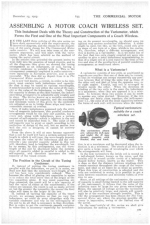
In the best varionteters the inside coil is wound on a ball-shaped former, known as the rotor, and the outside coil is wound otOthe inside of a sphericalshaped hollow former, known as the stator. This is done so that the distance between windings.shall remain constant throughout the range of the instrument, and shall at all times be as small as possible. When this type of con structiOn is adapted and the coils are connected in series, it.. is possible to get a ratio between maximum and minimum values of over nine to one.
Since, at all settings of the variometer, the amount of capacity is small (being limited to the self-capacity of the instrument), it follows that the value of the induction must be large for any given• wave-length. Hence, the amount Of voltage across the variometer will also.be relatively large, and signals will accordingly be of the maximum strength possible. This is why the arrangement has been chosen for The Commercial Motor set, wherethe. greatest possible efficiency is imperative, owing to the limited size of the aerial.
In the next i.of this seri ei" es we shall give instructions for making a variorneter.