


A Combined
Page 36
If you've noticed an error in this article please click here to report it so we can fix it.
Magnetic and Fabric Filter
A Résumé of Patent Specifications That Have Recently Been Published
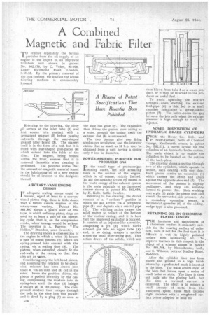
.17(remove separately the ferrous particles from the oil supply of an engine is the object of.. an improved filtration unit shown in patent No. 562,175, by C. Vokes, 95-105, Lower Richmond Road, London, S.W.15. By the primary removal of the iron content, the load on the actual fi:tering medium is considerably lessened
Referring to the drawing, the dirty arrives at the inlet tube (1) and first comes into contact with a permanent magnet (2) before passing outwards through the star-shaped pleatel filter fabric (3). The magnet itself is in the form of a rod, but it is fitted with star-shaped pole-pieces (4) which extend into the folds of the filter. The magnet, being housed within the filter, ensures that it is removed therewith when cleaning is performed. The patentee states that the amount of-magnetic material found in the lubricating oil of a new engine should be of interest to the designers thereof.
A ROTARY-VANE ENGINE DESIGN I F adequate sealing means could be devised, equal at least to a conventional piston ring, there is little doubt that a future• awaits engines of the rotary-vane variety. Patent No. 561,807 shows a power unit of this type, in which ordinary piston rings are used for at least a part of the operating cycle, that. is, on the compression stroke, when leakage would be serious. The inventor is A. Burrow, " The !lollies," Brandon, near Coventry.
The drawing shows a cross-section of the engine in which a rotor (1) houses a pair of round pistons (2), which are spring-pressed into contact with the casing, via a sealing shoe (3). The pistons, when extended, closely fit the end-walls of the casing so that they also act as wines.
Considering only the left-hand piston, and assuming the rotation to be clockwise, mixture has been drawn into space 4, via an inlet slot (5) cut in the rotor. From the position shwa, the piston is pushed inwardly by the casing, compressing the mixture into its spring-bore until the shoe (3) bridges a pocket (,6) in the casing. The compressed mixture then escapes through the hole in the shoe into this pocket, and is fired by a plug (7) so soon as
A34 the Shoe has gone by. The expansion then drives the piston, now acting as a vane, mound the Casing until the exhaust slot (8) is uncovered.
The two pistons give two firing strokes per revolution, and the inventor claims that as much as 18 h.p. may be obtained from a unit having a casing only 9 ins. in diameter.
POWER-ASSISTED PURIFIER FOR PRODUCER GAS
IN the usual type of producer-gas 'cleaning outfit, the sole actuating force is the. suction of the engine, which is, of course, strictly limited. To aid the cleaning action by means of the waste energy of the exhaust system is the main principle of an improved cleaner shown in patent No. 562,050, by K. Kalle, Saffle, Sweden.
Referring to the drawing, the device consists of a " cyclone " purifier in which the gas arrives via a peripheral pipe (1) and departs via a central pipe (2). The whirling action causes the solid matter to collect at the bottom of the conical casing, and it is here that the improved extractor is located. It consists of an injector-like assembly, comprising a jet (3) which blows exhaust gas into an upper tube (4) and, in so doing, creates a suction across the small intervening gap. This action draws off the solids, which am then blown from tube 5 as a waste product, or it may he returned to the producer as useful fuel.
To avoid upsetting the mixture strength when starting, the exhaust feed-pipe (6) is first led to a small chamber containing a spring-loaded piston (7). The latter.opens the gap between the jets only when the exhaust pressure is high enough to work the injector.
NOVEL DISPOSITION OF HYDRAULIC BRAKE CYLINDERS
FROM the Rover Co., Ltd., and P. Scott-Iversen, both of Chesford Grange, Kenilworth, comes, in patent No. 562,311, a novel layout for the cylinders of an hydraulic brake system. The main object is to enable the cylinders to be located on the outside of the back-plate.
The drawing shows a section through two of the cylinders, which operate in unison, each -dealing with one shoe. Each piston carries an extension (1) which crosses the other and abuts against the opposite shoe-end (2). The movement of the pistons is slightly oscillatory, and they are Suitably formed to permit this. Slots working over a pin (8) guide the piston rods and absorb the unwanted side pressure.' As asecondary operating means, a mechanical spreader (4) of the slidingwedge type is also provided.
RETAINING OIL ON CHROMIUM. PLATED LINERS
THE hardness and smoothness of chromium renders it eminently suitable for the wearing surface of cylinders, were it not for the fact that it is • difficult to wet its highly polished
surface with lubricating oil. To , improve Matters in this respect is the object of a scheme shown in patent No. 561,788, by Monochrome, Ltd., .and S. Wilsdon, both of Studley Road, Redditch.
After the cylinder liner has been plated and ground to a high finish internally, a perforated mask is inserted in the bore. The mask covers most of the bore but leaves open a series of small holes or slots. The liner is then pat back into the plating bath, but this time a reversed current is employed. The effect is to remove a small amount of metal from the uncovered sots; these then become slight recegses with a roughened surface better adapted to held oil.