


FEW the Orawing ppn Montgorr
Page 52
Page 53
If you've noticed an error in this article please click here to report it so we can fix it.
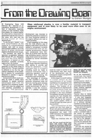
IN Engineering News (CM February 28) I reported on an interesting development in the field of alternative materials, namely an inlet manifold, made from plastic, for a petrol engine. As alternative materials for automotive use are very much in the news, let's look into the background of this development.
To use the term "plastic" is an over simplification as the material is a polypropylene maleate resin with an acrylic thermoplastic additive; it's in the family of glass reinforced plastics otherwise known as grp.
The manifold, the result of technical co-operation between BTR Permali RP Ltd, Fibreglass Ltd and the Ford Motor Corn pany, is based on the aluminium manifold currently used on the 1.31_ Cortina.
The use of plastics is confined generally to low stress areas of body and trim. The grp manifold is believed to be the first significant realisation of the potential of plastics for components designed to operate in aggressive environments.
Components which could possibly be made in plastic were reviewed to assess potential advantages both from the technical and marketing angles. There were also the weight and cost reduction possibilities to consider. This particular
development was intended to assess the potential of plastics in the more functional aspects of the engine without any cost or weight penalties.
It was suggested at this stage that the most effective way of keeping costs down would be to replace a component currently manufactured from an exmaterial, eg aluminium. Several such components were identified, all of which were die castings exhibiting severe undercut areas which could not be accommodated by normal retractable coring.
As all these components under study required machining after casting to provide seal faces for assembly, it was realised that if a plastic moulding could be made to machine tolerances then a machining operation could be eliminated thus reducing the production cost considerably.
One advantage of choosing the inlet manifold is that this particular component does not have any moving parts whereas the main disadvantage is the hostile environment in which it operates. It was felt, however, that if a plastics component
could be made to survive in an under-bonnet area, then much of the development cost for subsequent engine components would be obviated.
At this stage it is worth looking in closer detail at the requirements of an intake manifold as it is exposed to a lot more than just heat and vibration. The function of an inlet manifold is to distribute the air/fuel mixture from the carburettor. A hot spot is provided in the Ford manifold immediately beneath the carb to vaporise any fuel droplets that impact the walls and this hot
spot is heated by the engine's own coolant system, which is routed through the lower part of
the manifold.
The composition of the coolant can vary from water to 50 per cent glycol complete with anti-corrosion additives while its temperature can reach 110C (230F) because of its pressurised system running at 105kN/sqrn (15psi).
That's the chemical side; as
far as the mechanical E concerned, the manif subjected to the folic stresses: Compression (bolt ti fastening it to the head); Constant load (weig carburettor and air cleaner Creep (loading aggravat high temperatures); Fatigue (due to er vibration); Thermal (due to temp( variation during operation It was also suggeste impact strength should b that a spanner could be dr on it without damagin manifold as this was a pi occurrence during servicir These were the require' now for the material.
The fluctuating temp; under a constant load r( the choice of material thermoset plastic. 1-1i,q forrnance/hig h-cost themn tics had to be rejected ; epoxy resins, not only a grounds but because the also vulnerable to aqueo gradation.
Left with the choice bE polyesters and phenolic development engineers w the former as pre,.
nce had shown that the n-shrink range of these Is could be moulded very itely within machine 1;es. What remained an issue, however, was r a polyester compound be developed which offer an acceptable omise between good ice to both aqueous and icarbon (ie, fuel) ments.
e experimental manifold tended to fit a current for direct evaluation 3s it was obviously not le to make any major ication. Some mod Dns were necessary, and these included ribs between the headig flange and the carbubounting flange.
9 to the low thermal :ivity of plastic compared
to aluminium, it was necessary to mould in an aluminium hot spot directly below the carburetter flange.
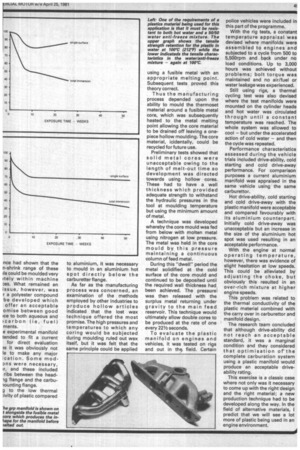
As far as the manufacturing process was concerned, an examination of the methods employed by other industries to produce hollow articles indicated that the lost wax technique offered the most promise. The high pressures and temperatures to which any coring would be subjected during moulding ruled out wax itself, but it was felt that the same principle could be applied Left: One of the requirements of a plastics material being used for this application is that it must be resistant to both hot water and a 50/50 water anti-freeze mixture. The upper graph shows the tensile strength retention for the plastic in water at 100°C (212°F) while the lower indicateds the tensile characteristics in the water/anti-freeze mixture — again at 100°C using a fusible metal with an appropriate melting point. Subsequent tests proved this theory correct.
Thus the manufacturing process depended upon the ability to mould the thermoset material around a fusible metal core, which was subsequently heated to the metal melting point allowing the core material to be drained off leaving a onepiece hollow moulding. The core material, icidentally, could be recycled for future use.
Preliminary tests showed that solid metal cores were unacceptable owing to the length of melt-out time so development was directed towards using hollow cores. These had to have a wall thickness which provided adequate strength to withstand the hydraulic pressures in the tool at moulding temperature but using the minimum amount of metal.
A technique was developed whereby the core mould was fed from below with molten metal using nitrogen at low pressure. The metal was held in the core mould by this pressure maintaining a continuous column of feed metal.
During this "dwell" period the metal solidified at the cold surface of the core mould and continued to be deposited until the required wall thickness had
been achieved. The pressurel was then released with the surplus metal returning under gravity to the main feed reservoir. This technique would ultimately allow double cores to be produced at the rate of one every 221/2 seconds.
To evaluate the plastic manifold on engines and vehicles, it was tested on rigs and out in the, field. Certain police vehicles were included in this part of the programme.
With the rig tests, a constant temperature appraisal was devised where manifolds were assembled to engines and subjected to a cycle from 500 to 5,500rpm and back under no load conditions. Up to 3,000 hours was achieved without problems; bolt torque was maintained and no air/fuel or water leakage was experienced.
Still using rigs, a thermal cycling test was also devised where the test manifolds were mounted on the cylinder heads and hot water was circulated through until a constant temperature was reached. The whole system was allowed to cool — but under the accelerated action of cold water — and then the cycle was repeated.
Performance characteristics assessed during the vehicle trials included drive-ability, cold starting and cold drive-away performance. For comparison purposes a current aluminium manifold was appraised in the same vehicle using the same carburettor.
Hot drive-ability, cold starting and cold drive-away with the plastic manifold were acceptable and compared favourably with its aluminium counterpart. Initially cold drive-away was unacceptable but an increase in the size of the aluminium hot spot was used resulting in an acceptable performance.
With the engine at normal operating temperature, however, there was evidence of slight hesitation at low speeds. This could be alleviated by adjusting the choke, but obviously this resulted in an over-rich mixture at higher engine speeds.
This problem was related to the thermal conductivity of the plastic material combined with the carry over in carburettor and manifold design.
The research team concluded that although drive-ability did not reach an acceptable standard, it was a marginal condition and they considered that optimisation of the complete carburation system using a plastic manifold would produce an acceptable driveability rating.
This exercise is a classic case where not only was it necessary to come up with the right design and the right material; a new production technique had to be developed along the way. In the field of alternative materials, I predict that we will see a lot more of plastic being used in an engine environment.