


.Controlling Power Distribution to, Front and Rear Axles
Page 42
If you've noticed an error in this article please click here to report it so we can fix it.
PATENT N. 554,404 chines from the Four Wheel Drive Auto Co , Clintonville, Wisconsin, U.S.A., and refers to the -heaviest class of road vehicle, in particular those having two front wheels and eight rear wheels, all of ,Which are driven. With such a vehicle, the patent states, it is usual to emptoy a differential wbich primarily divides the drive between the front two and the rear eight wheels, and this division is in the ratio of 1 to 5; that is, the rear wheels receive four-fifths of the power. Whilst this is suitable for a full load, it may cause wheel-spin with an empty vehicle, and it is, therefore, proposed to provide a second ratio in which the front wheels reoeive half the power and the other half goes to the rear group.
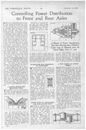
In the drawing, sprocket 4 is the input member and shafts 3 and 8 the two output members: The sprocket drives the casing (11). which carries the usual pin (1) on which the bevels are mounted. Each Each of the bevel .pinions has two working diameters, one meshing with a largo bevel (2) on output shalt 3, whilst the other rneshes with a smaller bevel (5) on a free shaft
(6). The power is thus distributed between the two shafts in the ratio of the bevel diameters, that is, 5 to 1.
A second lerge bevel (10) is sleeved on shaft 6 and is fitted with dog teeth (7). A sliding dog (9) operable from outside is splined on shaft 8 and can he moved to one of three positions to the left, where' it brings in the 5-to-1 ratio by coupling free shaft 6 to output shaft 8; to the centre, in which one large bevel (10 and 2) is coupled to each shaft, a position giving a 50/50 division of power The third position, , to the right, couples shaft 8 directly to the drive without differential action at all.
. A KEYING DEVICE FOR DEFLATED TYRES .
I NFLATING ktyre riot only enables it to carry its load, but also thrusts the bead into driving connection with the sides of the rim. In the. event of a
burst, the latter condition ceases to exist, and it is quite possible for relative rotation to do serious damage, such as tearing out the valve, before; the vehicle can be brought to rest. To provide a means for keying, independent of inflation pressure, is the object of an idea covered in patent No. 554,961 by the Iqrestene Tire and Rubber Co., Akron, Ohio, U.S.A.
A32 . The device is intended 'for use only with rims having one detachable side-wall, and the drawing shows a sectioned assembly on • such a' rim. Between the two tyre beads is placed a flexible metal band (1), on which is fitted, at definite intervals, a number of channel-section blocks (2). These are provided with serrated projections (3) which, under pressure from the bolted-on rim, dig into the bead and form a positive key.
WATER-PUMP SEAL REQUIRING NO ADJUSTMENT
WATER-CIRCULATING pumpsare W provided with some form of sealing gland, and this has to be adjusted from time to time. An improved pattern, requiring • no adjustment, is shown in patent No. 555,045, by Crane Packing, Ltd., _woo r Slough. Bucks. The Proposed washer, which can be assembled as a unit:consists • of a moulded-rubber bellows portion (2) surrounded by a light helical spring (1). The b61lows portion is riacated
between the .moving face of the impeller and a stationary face on the casing and, being clear of the shaft, can move independently of both. the resilience of the rubber and the spring' is sufficient to render the device selfadjusting throughout the whole of its useful life.
PISTON WITH AN ADJUSTABLE AND REPLACEABLE SKIRT
PATENT No, 554,912 shows a design of bi-metal piston in which the skirt is made in two parts and can be packed out to any desired, degree of fit. The patentees are William Mills, Ltd., Grove. Street, Birmingham, 18, and ' G. Agrtimer. Referring to the drawing, the ring-carrying portion and the gudgeon-pin boSses form a one-piece casting in light alloy. The skirt consists of a pair of semi-circular pieces (2), which are located
-on the outer. diameter (1) of the gudgeon . bosses. The skirt may be made of steel and may carry a. ringgroove at the lower end. By evasheringout -the skirt pieces, the effective diameter may beincreased to take up slack. The skirt may also be. replaced.
A NEW DESIGN OF SPRING WHEEL.
QHORTAGE of rubber has had the
effect of revivifying the interest 'of inventors in the possibilities of the spring wheel, and patent N. 554.956 shows the latest idea on the subject. The patentee is H. 'Deane, 231, Bristol Road, Birmingham, 5. This inventor proposes to use a disc,extending from the hub and sandwiched between a pair of 'rings attached to.the-rim. The two tia.rts are ,located 'concentrically by. a . resilient coupling, which is displaceable under. shock.
The drawing sboWs a vieW looking down on.the wheel, with the.rim partly ,cut away. The wheel itself, which is Part. of the hub, is shown as a hollowsection member (4-) having flat outer faces. A close fit on these is the rim • proper, consisting 'of a pair of sings (3 and 5), held together by spacing studs (1). This rim member is dimpled at many points around its sides, and each dimple (6) receives a spring-loaded conical plunger (2) which is a sliding fit in the wheel member (4). • Normally, the plungers hold the rim concentric with the 'wheel, but under shockthe rim, by compressing the plunger springs, can retreat slightly in any direction.