


Decarbonizing By. Orderly Sequence S IMPLE as may oe the operation
Page 41
If you've noticed an error in this article please click here to report it so we can fix it.
ef decarbonizing the average.engine, orderly methods will greatly reduce the possibilities of the work being impeded as the result of endeavours being made to remove a component out of :sequence. Asthere is a correct *order of assembly, so . there is in dismantling, and,, if this procedure be followed, considerable time will be saved in carrying out the work. The' present • article is concerned with the Mofris' Commercial C.V. 11/40 model, and by keeping to 'the numbered sequence, as here given, the work should be, considerably simplified 1, The bonnet need not be removed, as practically every operation can be carried out with only the near side of -the bOnnet lifted.
2 Drain water from the radiator by means of the' drain tap, and, from the cylinder block, by removal of the plug in the bottom of the water jacket on the off. side.
3. Remove the top rubber hose between the engine and radiator.
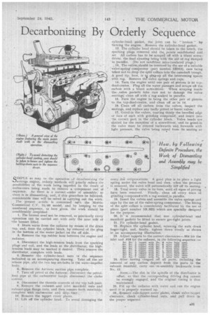
4. Disconnect the 'high-tension leads from the sparking plugs and coil, and the leads at the distributor; the hightension leads May be marked if desired. Then remove the distributor, complete with leads: 5.'Remove the cylinder-head nuts in the sequence indicated in an accompanying drawing. Take off the air release pipe, atisl the two top set-bolts in the water-impeller body.
6. Remove the Antovac suction pipe, complete..
7. Turn off petrol at the Autovac; disconnect the petrolfeed pipe at the carburetter bank); disconnect the choke control.
8. Disconnect the throttle controls at the topball-joint.
9. Remove the exhaust and inlet manifold nuts and exhaust-pipe flange nuts, and then remove -both manifolds, completewith carburetter and drip tray. ,
10. Remove the tappet cover plates.
11: Lift off the cylinder head. To avoid damaging the cylinder-head gasket, the joint can be "broken " by turning the engine. Remove the cylinder-head gasket.
12. The cylinder head .should be taken to the bench, the sparking plugs removed ahd the points sandblasted and set All carbon has to be scraped off with a blunt screwdriver, the final cleaning being with the aid of rag damped in paraffin. (Do not sandblast mica-insulated plugs.)
1-3. The valves,shotild be removed by the use of a suitable valve-spring compressor (part number SR313), care being taken not to drop the split collars into the camshaft trough. A good tip, here, is tg plug-up all the intervening spaces with rag. Remove the valve springs and caps.
14. Turn the engine until one pair of pistons is at topdead-centre. Plug all the water passages and scrape off the carbon with a blunt scfewdriver. When scraping inside the • valve pockets take care not to damage the valve seatings; clean off with a rag soaked in paraffin, • 15. Turn the engine to bring the other pair of pistons to the top-dead-Centre, and clean off as in 14.
16. Clean off all carbon from the valves, inspect the se,atings, and replace any badly pitted of burnt valves 17.. Grind-in the valves, coating thinly the bevelled edge or face of each with grinding compound, , and insert into the correct port in the cylinder block. Valve heads are _ . slotted for the reception of a screwdriver, and to grind-in the valve Must be rotated backwards and forwards with • light pressure, the valve, being raised from its seating at
every .,fe; reciprocations. A good plan is to place a light spring under the valve head and then, when the pressure is removed, the valve will automatically lift off its seating.
18. Treat every valve in its turn, until all signs of pitting have been removed. Finally, clean off etrery trace of grinding compound with a rag soakekin paraffin.
19. Insert the valves and assemble the valve springs and caps by the use of the vaIve-spring compressor. The fitting of the split collars is considerably facilitated by the use of pliers (part number SR.322) which .are specially designed for the purpose.
20. It is recommended that new cylindef-head and manifold gaskets be fitted to ensure gas-tight joints.
21. Fit cylinder-head, gasket. 22—Replace tlle cylinder head, screwing the nuts down finger-tight, and, finally, tighten down evenly as shown in an accompanying illustration. .
23. Adjust tappets to the correct clearances—.004 for the inlet -and .018 for the exhaust, in the following sequence:— Set No. 1 tappet with No, 8 valve fully open. Set No. 3 tappet with No. 6 valve fully open. Set No. 5 tappet with Na 4 valve fully open. Set No, 2 tappet with No.' 7 valve fully open. Set No. 8 tappet with Na. 1 valve fully open. Set No. 6 tappet with No. 3' valve fully open. Set No. 4 tappet with No, 5 valvefully open. Set No. 7 tappet with No. 2 valve fully open.
24. After having clea.ned off all parts, including the removal of any carbon deposit from the ports in the 'exhaust manifold, carry out -re-assembly backwards from No, 12.
NOTE.—The slot in the spindle of the distributor is offset, so that the corresponding driving dog cannot be wrongly engaged, and the original timing is thus maintained.
25. Fill up the radiator with water and run the engine until it is properly warmed up. 26.. Remove vale-tappet cover'plates, check valve-tappet clearance, check cylinder-head nuts, and pull doU n in the proper sequence.