


PROPORTIONING THE MIXTURE MECHANICALLY.
Page 30
If you've noticed an error in this article please click here to report it so we can fix it.
A Résumé of Recently Published Patents.
ASYSTEM of carbuietter control, in which the separate levers control. iug, the fuel and air supplies are so coupled, with arrangement for convenient lost-motion effects, that they cause due and proper proportioning of the fuel and air in the combustible mixture, is described by La Carburation Par le
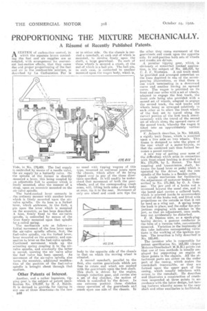
Vide, in NO. 17%401. The fuel supply is controlled by means of a, needle valve, the air supply by a, butterfly valve. On the spindle of the former is directly mounted a lever, this being coupled by an adjustable link to another which is freely mounted, after the manner of a strap, upon an eccentric mounted on the air-valve spindle.
The hand-control lever connects in theordinary manner with another lever which is freely mounted upon the airvalve spindle. On its boss is a forked lever, which embraces, in the fork, a pin upon the lever which is mounted on the eccentric, as has been described. A hoes, firmly fixed to the air-valve spindle, is controlled by means of the !ever freely mounted upon that spindle by .a coiled spring. • The mechanism acts as follows :Initial movement of the free lever upon the air-valve spindle affects, first, the fuel-valve spindle, via the forked lever, lever mounted on the eccentric, and connection to lever on the fuel-valve spindle. Continued movement winds up the actuating spring emipling it to the air. valve spindle, and. eventually the latter is moved, opening the air valve after the fuel valve has been opened. As movement of the air-valve spindle also turns the eccentric,additional modification of the position of the fuel-valve spindle is brought about through that medium.
Other Patents of Interest.
Another, and a rather ingenious, tip. ping gear is the subject of patent specification No. 179,897, by IL J. !Statile. It is devised to provide for tipping in any one of three directions—to the rear
B1.43
or to either side. On the chassis is carried a camshaft at each end of which is mounted, to revolve freely upon the shaft, a large gearwheel. To each of these wheels is secured a crank, at the end of which is a ball pin. The ball pin, in each case, is connected to another mounted upon the wagon body, which is,
as usual with tipping wagons of this type, mounted on universal joints upon the chassis, which allow of its being tipped over in any of the three directions specified. It will readily be understood that movement of both the gearwheels, and of the corresponding crank arms, will, lifting both sides of the body at once, tip it to the rear. Movement of only one wheel and crank arm tips the body to the opposite side of the chassis to that on which the moving wheel is situated.
A. second camshaft, parallel to the first, also carries gearwheels which are free to rotate and which are meshed with the gearwheels upon the first shaft. This shaft is driven by the engine, through reduction gear, and carries also a set of dog clutches, the motion of which is controlled by the driver. In one extreme position these clutches cause operation of the gearwheels and crank upon one side of the chassis. In the other they cause movement of the gearwheels and crank upon the oppoSite side; 1h mid-position both sets Of e-heels and cranks are driven.
A peculiar tipping gear, which is obviously of somewhat limited application, is the subject of No. 185,524, by C. J. F. Westman. A rail track must be provided and arranged somewhat on the lines depicted in one of the accompanying illustrations, so that there is one track terminating in a downward curve and another having an upward curve. The wagon is provided on its front and rear axles wit-ha set of wheels, adapted to engage the first track, the front axle beingalso provided with a second set Of wheels, adapted to engage the second track, the said tracks and wheels being so arranged relatively to each other as to allow the front wheels of the first set to travel along the curved portion of the first track simultaneously with the travel of the second set of wheels along the upward curve of the second track, whereby the wagon is tilted into an approximately vertical position.
F. AChurch describes, in No 185,613, a rigidly built frame, which is mounted upon a live axle on two wheels. This frame is designed to take the place of the rear wheel of a motorAlicycle' so that the combined unit thus formed becomes a parcel carrier.
A new way of getting over some of the difficulties which arise in connection with front-wheel braking is described in No. 175,276, by L. Hersot. The final coupling and transmission shaft, between the hand lever or pedal which is operated by the driver, and the cam spindle of the brake is a flexible cable. A simple mechanism for facilitating the adjustment of motorcar brakes is described in No. 171,968, by G. A. Gemmel.. The jaw end of a brake rod is increased beyond the usual size, and in the bored pert carries a collared bush, which is screwed inside to accommodate the end of the brake rod, and fitted with projections on the outside so that it can be used as a wing nut. A spring keeps the bush in place, and the collar has projections engaging with notches in the jaw, so that an adjustment, once made, may not. accidentally be disturbed. M. Denton uses, as a. spark-plugtesting device, a gaseous conductor in the form of a vacuum tube, conveniently mounted. Variation in the luminosity of this tube indicates corresponding .variaCons in the working of the ignition system. The invention is fully described in No. 185,441.
The inventor who is responsible for patent •specification No. 163,331 (Argus Motoreirgesellschaft 141.13.11.) points but that one of two methods is usually employed • for supporting an engine at three points in the chassis. All the attachment parts are either on the under part of the casing, which makes the crankshaft inaccessible, or they are formed upon the upper part of the casing, which usually interferes with access .to the camshaft. lie describes and illustrates a construction of crankcase suspended at three points in accordance-with the latter design, but hay-lug features whereby access to the camshaft and other auxiliaries is facilitated.