 1
1 2
2 3
3 4
4 5
5 6
6 7
7 8
8 9
9 10
10 11
11 12
12 13
13 14
14 15
15 16
16 17
17 18
18 19
19 20
20 21
21 22
22 23
23 24
24 25
25 26
26 27
27 28
28 29
29 30
30 31
31 32
32 33
33 34
34 35
35 36
36 37
37 38
38 39
39 40
40 41
41 42
42 43
43 44
44 45
45 46
46 47
47 48
48 49
49 50
50 51
51 52
52 53
53 54
54 55
55 56
56 57
57 58
58 59
59 60
60 61
61 62
62 63
63 64
64 65
65 66
66 67
67 68
68 69
69 70
70 71
71 72
72 73
73 74
74 75
75 76
76 77
77 78
78 79
79 80
80 81
81 82
82 83
83 84
84 85
85 86
86 87
87 88
88 89
89 90
90 91
91 92
92 93
93 94
94 95
95 96
96 97
97 98
98 99
99 100
100 101
101 102
102 103
103 104
104 105
105 106
106 107
107 108
108 109
109 110
110 111
111 112
112 113
113 114
114 115
115 116
116 117
117 118
118 119
119 120
120 121
121 122
122 123
123 124
124 125
125 126
126 127
127 128
128 129
129 130
130 131
131 132
132 133
133 134
134 135
135 136
136 137
137 138
138 139
139 140
140 141
141 142
142 143
143 144
144 145
145 146
146 147
147 148
148 road and workshop
Page 49
If you've noticed an error in this article please click here to report it so we can fix it.
by Handyman
Auto-electrics for the mechanic (12)
THERE is little doubt that the component with the toughest job on the road transport vehicle is the starter motor. It is expected, and of course designed, to operate at maximum torque at standstill. After coping with the breakaway drag of a large cold engine it has then to continue exerting a driving torque in excess of the resistance put up by engine compression and oil drag.
A considerable power, and hence a very high current must therefore be supplied to this motor. The motor is usually arranged with four field coils or poles and these are connected in series with the armature windings so that the current in both field and armature coils is equal. This arrangement, known as the series dc motor, provides the right torque requirements and has proved to be the best for the job in hand.
Operation
In operation, full battery voltage is applied across the field and armature coils which are both of low resistance. The magnetic fields of the armature and field interact with each other to produce the strong armature torque, which enables the armature to revolve against heavy engine Load. As the motor overcomes the starting torque of the engine, the demand on the battery decreases as the motor speeds up to -cranking revolutions. The reason for the reduction in current is because the spinning armature conductors are now cutting the magnetic lines of force inducing a voltage which is in opposition to the battery current. This voltage, sometimes called a back e.m.f. increases with the armature speed.
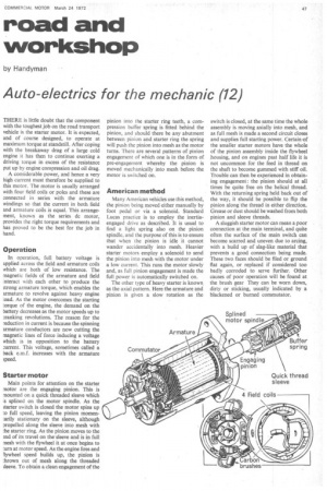
Starter motor
Main points for attention on the starter motor are the engaging pinion. This is mounted on a quick threaded sleeve which is splined on the motor spindle. As the starter switch is closed the motor spins up to full speed, leaving the pinion momentarily stationary on the sleeve, although propelled along the sleeve into mesh with the starter ring. As the pinion moves to the !rid of its travel on the sleeve and is in full mesh with the flywheel it at once begins to turn at motor speed. As the engine fires and Flywheel speed builds up, the pinion is thrown out of mesh along the threaded sleeve. To obtain a clean engagement of the pinion into the starter ring teeth, a compression buffer spring is fitted behind the pinion, and should there be any abutment between pinion and starter ring the spring will push the pinion into mesh as the motor turns. There are several patterns of pinion engagement of which one is in the form of pre-engagement whereby the pinion is moved mechanically into mesh before the motor is switched on.
American method
Many American vehicles use this method, the pinion being moved either manually by foot pedal or via a solenoid. Standard Lucas practice is to employ the inertiaengaged drive as described. It is usual to find a light spring also on the pinion spindle, and the purpose of this is to ensure that when the pinion is idle it cannot wander accidentally into mesh. Heavier starter motors employ a solenoid to send the pinion into mesh with the motor under a low current. This runs the motor slowly and, as full pinion engagement is made the full power is automatically switched on.
The other type of heavy starter is known, as the axial pattern. Here the armature and pinion is given a slow rotation as the switch is closed, at the same time the whole assembly is moving axially into mesh, and as full mesh is made a second circuit closes and supplies full starting power. Certain .of the smaller starter motors have the whole of the pinion assembly inside the flywheel housing, and on engines past half life it is not uncommon for the feed in thread on the shaft to become gummed with stiff oil. Trouble can then be experienced in obtaining engagement: the pinion should at all times be quite free on the helical thread. With the returning spring held back out of the way, it should be possible to flip the pinion along the thread in either direction. Grease or dust should be washed from both pinion and sleeve threads.
A sluggish starter motor can mean a poor connection at the main terminal, and quite often the surface of the main switch can become scarred and uneven due to arcing, with a build up of slag-like material that prevents a good connection being made. These two faces should be filed or ground flat again, or replaced if considered too badly corroded to serve further. Other causes of poor operation will be found at the brush gear They can be worn down, dirty or sticking, usually indicated by a blackened or burned commutator.