


Lost-motion Coupling
Page 70
If you've noticed an error in this article please click here to report it so we can fix it.
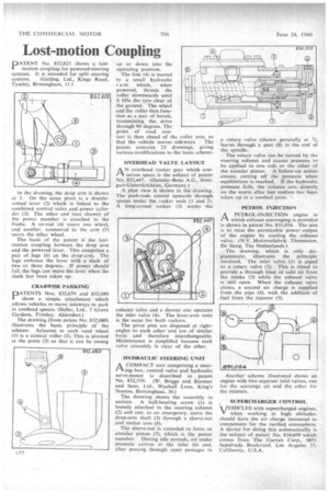
DATENT No. 832,825 shows a lostmotion coupling for powered-steering systems. It is intended for split steering
systems. (Girling, Ltd., Kings Road, Tyseley, Birmingham, IL) In the drawing, the drop arm is shown at I. On the same pivot is a doublearmed lever (2) which is linked to the combined control valve and power cylinder (3). The other end (not shown) of the power member is attached to the frame. A tie-rod (4) steers one wheel, and another, connected to the arm (5) steers the other wheel.
The basis of the patent is the lostmotion coupling between the drop arm and the powered lever. This comprises a pair of lugs (6) on the drop-arm. The lugs embrace the lever with a slack of two or three degrees. If power should fail, the lugs can move the lever when the slack has been taken up.
CRABWISE PARKING
PATENTS Nos. 832,679 and 832,680 show a simple attachment which allows vehicles to move sideways to park in confined spaces. (Sidler, Ltd., 7 Grove Gardens, Frimley, Aldershot)
The drawing (from patent No. 832,680) illustrates the basic principle of the scheme. Adjacent to each road wheel (1) is a conical roller (2). This is pivoted at the point (3) so that it can be swung up or down into the operating position.
The link (4) is moved by a small hydraulic r a m which, when powered, thrusts the roller downwards until it lifts the tyre clear of the ground. The wheel and the roller then function as a pair of bevels. transmitting the drive through 90 degrees. The point of road contact is then ahead of the roller axis, so that the vehicle moves sideways, The patent contains 23 drawings, giving various modifications to the basic scheme.
OVERHEAD VALVE LAYOUT
AN overhead rocker gear which conserves space is the subject of patent No. 832,447. (Daimler-Benz A.G., Stuttgart-Untertiirkheim, Germany.)
A plan view is shown in the drawing. The push-rods extend upwards through spaces under the rocker ends (1 and 2). A long-armed rocker (3) works the exhaust valve and a shorter one operates the inlet valve (4). The lever-arm ratio is the same for both rockers.
The pivot pins are disposed at rightangles to each other and are of similar form and therefore interchangeable. Maintenance is simplified because each valve assembly is clear of the other.
HYDRAULIC STEERING UNIT
A COMPACT unit comprising a steering box, control valve and hydraulic servo-motor is described in patent No. 832,559. (W. Briggs and Burman and Sons, Ltd., Wychall Lane, King's Norton, Birmingham, 30)
The drawing shows the assembly in section. A ball-bearing screw (1) is loosely attached to the steering column (2) and can, in an emergency, move the drop-arm shaft (3) through a sleeve-nut and rocker arm (4).
The sleeve-nut is extended to form an annular piston (5), which is the power member. During idle periods, oil under pressure arrives at the inlet (6) and, after passing through open passages in a rotary valve (shown generally at 7), leaves through a port (8) in the end of the spindle.
The rotary. valve can be turned by the steering column and causes pressure to be applied to one side or the other of the annular piston. A follow-up action ensues, cutting off the pressure when equilibrium is reached. If the hydraulic pressure fails, the column acts directly on the worm after lost motion has been taken up in a toothed joint.
PETROL INJECTION
A PETROL-INJECTION engine in 1-1 which exhaust scavenging is provided is shown in patent No. 831,054. The aim is to raise the permissible power output of the engine by cooling the exhaust valve. (N.V. Motorenfabrik Thomassen, De Steeg, The Netherlands.) The drawing, which is only diagrammatic, illustrates the principle involved. The inlet valve (1) is piped to a rotary valve (2). This is timed to provide a through blast of cold air from the intake (3) while the exhaust valve is still open. When the exhaust valve closes, a second air charge is supplied from the pipe (4), with the addition of fuel from the injector (5).
Another scheme illustrated shows an engine with two separate inlet valves, one for the scavenge air and the other for the mixture.
SUPERCHARGER CONTROL
VEHICLES with supercharged engines,
V when working at high altitudes, should have the air charge increased to compensate for the rarified atmosphere. A device for doing this automatically is the subject of patent No. 834,609 which comes from The Garratt Corp., 9851 Sepulveda Boulevard, Los Angeles 25, California, U.S.A.