


A 200 h.p. Petrol-electric Railcoach.
Page 21
Page 22
If you've noticed an error in this article please click here to report it so we can fix it.
We Witness Preliminary Trials before Its Shioment to New Zealand.
That special form of power transmission known as the Thomas has for a number of years past been a subject of special interest to the staff of THE COMMERCIAL MOTOR, and to its readers through our pages. In our issue for the 17th June, 1909, which, at the time of writing, is, " as near as makes DO matter," six years ago, we described the Leyland four-tonner to which the first practical exposition of this transmission system was applied. That actual machine did noteworthy experimental and demonstration work for two years, and, subsequently, actually took part in a 2000 miles test under R.A.C. observation in the middle of 1911. The result of that test was, as many of our readers will recall, the establishment of a tonmileage record for highway operation which reached the figure of 67.92 ton-miles per gallon of fuel consumed, a performance which has not been excelled or even equalled since that date. That in itself was sufficient concrete evidence of the fact that the transmission gear was right in principle, and we have not sinee that time lost our faith in it. At a later period,' the inventors were induced to turn their attention to the adaptation of this combined mechanical and electrical gear as part and parcel of the propelling equipment of independent railooaches Experience on the South African railways, with a 160 h.p. railcar, has put the seal of success upon the principle, for this particular purpose.
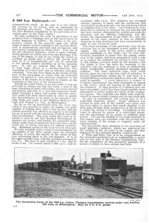
We have now had an opportunity of examining the first of a new and improved type of railcar, which has been completed for early delivery to the New Zealand Government Raihiray authorities, and in this example, which, incidentally, we were privileged to test cn the rails for a short distance, the Thomas Transmission system appears to have reached a stage which should lend itself quickly to widespread adoption for similar purposes.
The system as applied to the new coach is, in all but small details, identical with that which has been developed for several years past.We have described and illustrated it on several occasions, and we need not set down in this instance, at any length, further repetition of the mechanical functions of the method adopted. Suffice it then for us to repeat that the
combination is one of electrical and Mechanical units, which enables an infinitely variable speed combination to be achieved, and which, at the same time, provides that for by far the largest proportion Of the run:, flingthe minimum transmission loss shall be recorded.
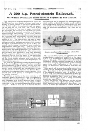
The lay-out of the system, as applied to this New Zealand coach, is effectively displayed in the reproduction of a diagrammatic drawing which appear*. below on this page. This simple outline drawing, conjunction with the excellent photograph of the chine on its trial trip, as reproduced on, the opposite' page, yields ready explanation of the manner in which the mechanical and electrical units are dig.: posed.
There are, it will be seen, two totally-enclosed-dee; trical Machines, and these weigh about 15 cwt. each only. Then there is the drum enclosing the whole of the epicyclic reduction gear. A novelty in connection with this particular installation is the employment of electro-magnetic clutches in place of the ordinary mechanical ones which have been used hitherto. These appeal to us as being particularly suitable for plant of this size.
It may be recalled that reversing on the original Leyland machine was effected by purely electrical means that were quite sufficient for an ordinary road vehicle on which the amount of reverse driving is comparatively small. In the case of a rail vehicle the reverse is, of course, just as important as the forward movement. This has been effected in the New Zealand installation by the provision of reversing gear on the Tylor engine.
We may summarize the cycle of operations in the progress from a standing start to full speed ahead in simple language as follows :—By means of the progressive control of the epicyclic gear, the whole range of speed, as from starting to full in either direction, is progressively electrical and mechanical, and then purely mechanical by direct drive. That one of the two electrical machines, which is quite independently geared, as will be seen from the drawings, with one of the bogies, is only in use whilst the vehicle is
i
building up speed, and s driven idly during such time as it is automatically .put out of operation by the careful relative speeding up of the epicyclic gear. It will be noticed that the final gear of both bogie drives is a double-reduction one, consisting of a bevel pair and an ultimate spur-gear reduction. Care has been taken in the design of this part of the mechanism to insure that the universal Joints are placed in such positions relatively to the centres of the bogies as to impose no strains on the mounting of this part of the mechanism.
During the trials which, as we have said, it was our privilege to witness one day last week, a load of 120 tons, consisting of laden coal trucks, was easily started and hauled, and that on a very bad temporary track, which included a sharp and poorly elevated curve. This track had been constructed in order to enable this demonstration to be made in the extensive running sheds and yards of tho Midland Railway Carriage and Wagon Co., Ltd., at Birmingham. So far as can be ascertained from the short runs which it was possible to make, the engine was quite capable of looking after such a load as this, and the tiontrol certainly was effective in regard to the building up of speed with the minimum of shock and sufficient acceleration. The tests which this coach is required to pass by the New Zealand Government inspectors are -severe, and include the successful negoI iation under load of gradients of no less than 1 in 40, which are, of course, excessive for railway construction. Maximum speed on the level is to be 40 m.p.h. We may conclude with a word of commendation for the makers of the Tylor engine, upon the all-round efficiency of which the 'success of the whole of this very interesting plant in the end depends. It is of the eight-cylinder type, with the cylinders arranged in true Vs. The bore of each cylinder is 7 ins., and its stroke 8 ins. Its normal speed is 900 r.p.m., and its
maximum 1500 r.p.m. The cylinders are arranged directly opposite in pairs, and the connecting rods run inpairs on thesame pin, one big end being forked to embrace that of the other. Any tendency to overheat due to rubbing as between big end and big end has been entirely eliminated by careful provision for clearance and for effective lubrication, and Mr. 'White, the representative of the Tylor Co., who was present at the tests, assured us that no difficulty whatever in that direction had been encountered, in spite of very strenuous tests. .
The chief _advantage of this particular type of construction lies in the decreased overall length of the engine. The whole of this power plant is snugly stowed amidships in the frame, and 'we were particularly interested to notice how the piping, accessory to the engine, had been arranged in such a way as to reduce the necessity for extensive head room. A still further provision made by the designer with this object in view has been the recessing of the cylinders into the crankcase, a form of construction which, incidentally, insures increased strength and stillness. The main induction pipe, from which branch pipes are led to the two rows of cylinders, is located longitudinally inside the V. and there is a Claudel-Hobson carburetter fitted to each end ; these work in parallel. A novel departure in respect of V-engine construction has been embodied in regard to the valves, which are located on the outsides of the cylinders-. In that position it is claimed they are more accessible, and it has been found possible more adequately to water jacket the whole of the combustion spaces. The camshafts are fitted with small flywheels to ensure steady running and obviate back-lash.
As may be anticipated, the cooling gear is of a somewhat elaborate nature. Large radiators are located at each end of the vehicle, and great care has been taken to ensure that ample draught of air shall pass through them irrespective of the direction in which the vehicle is travelling. Circulation of the water is effected by means of a centrifugal pump, and the lubricating oil by means of ordinary gear pumps. The special method of reversing adopted on this engine does not interfere with the normal forward running of the pumps. or magneto under all circumstances.
We may finally draw attention to the provision of small auxiliary radiators, which are employed for the cooling of the oil used in the engine and that employed. in theepicyclio gearbox respectively.
J. Tylor and Sons, Ltd., is to be congratulated on the successful production of so workmanlike a power unit no less than is the Thomas Transmission, Ltd., for the completion of this successful example of a system in which we have always had faith.