


DEVELOPING THE TRACTOR-LORRY.
Page 32
If you've noticed an error in this article please click here to report it so we can fix it.
A Résumé of Recently Published Patents.
THE ATTENTION of a good many inventors is obviously focused upon the design of the six-wheeled tractor-trailer --combination. We referred last week to a couple of specifications, for which the well-known firm of 'Scammell. and Nephew were responaible, dealing with this subject.. This week there are three such patents by other inventors.
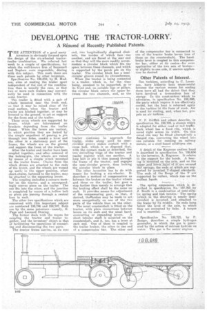
Specification No. 198,818, by H. Hudson, aims at making the trailer niore
independent of the rest of the combination than is usually the case, so that two or more such trailers may conveniently be used in connection with the sametractor.
The trailer is fitted with a pair of wheels mounted near the front end, so that it may be raised clear of the road surface, when the tractor and trailer are hitched together, or may be lowered to the ground, to act as support for the front end of the trailer.
These extra wheels are supported by levers, which are fulcrurnmed on brackets depending from . the trailer .
frame. When the levers are vertical, in which position they are locked by the simple expedient of, passing a pie through two holes, ono-in alever and the other in a , stationary part of the frame, the wheels are on the ground and support the front of the tra.ctor.
After' the trailer and tractor have been coupled together, anell after removal of. the locking-pin, the wheels are raised by means of a' simple winch mounted'
cm the trailer frame. Chains from the Winch drums are attached to the ends
of the levers, and the wheels are wound uri until; in -the upper position, other short-chains, fastened to the trailer, may, be attached to the supporting levers.
The coupling embodies a concave men'her on the tractor; and a correspond-. • ingly convex piece on the trailer. The one fits,into the other, and the junction is completed by means of a,hollow belt or pivot pin passing through , a central boss in each.
The other two specifications which, are concerned with this important subject
are numbered 198;746 and 198,747. Both are by the same patentees—nameIa-, G. Page and Leonard Dewing.
The former deals with the means for coupling the tractor and trailer to gether, and the inventors' object is that of facilitating the operations of connecting and disconnecting the two parts.: The tractor frame carries, at its l'ear end, two longitudinally disposed channels, the insides of Which face ' one another, and are flared atthe rear end so that they will the more readily accommodate a circular block which fits the space between these channels, and which is supported by the perch pin On the trailer. The circular block has a semicircular groove round its circumference, When the tractor is being connected to a trailer, which is, for the time being, assumed to be supported, as to its front end, on suitable legs or pillars, the circular block enters the spacebetween the two channels, and, as the
traitor continues to approach the trailer, slides along • until its semicircular groove Makes Contact 'with a cross bolt, which. is so disposed that, with the contact, made as described, the two' Swivelling rings Of the tractor and trailer , register with.. one another. A long bolt or 'pin is then passed through the frame of the tractor, and engages the semi-circular groove, thus locking the circular block in place.
The Other invention has to do with means " for braking a six-wheeler. It describes a method of compensation as between the brakes on the tractor wheels and those on the trailer, but goes a step farther than merely to arrange that the braking effect shall be the same on each. It provides means for adjustment of the compensating gear, so that, if desired, theabrakes may be made to act more energetically on one of the two parts of the vehicle than on the other.
The usual countershaft is fitted on the tractor, with plain connections between levers on its ends and the usual band contracting or expanding levers. A short tubular shaft is mounted on the countershaft, and it, too, has a lever at each end. One of them is coupled to the trailer brakas, the other to one end of a compensator bar: The. other end of the compensator bar is connected to one of the tractor brake levers (one of those on the coontershaft). The hand.brake levee is coupled to this compensator bar, either at its centre—for even appliCation of the two sets of brakes— or Slightly_to one side, if uneven application 'be desired.
Other Patents of Interest.
Gas turbines, according to C. Lorenzen, have hitherto been unsuccessful. because the varions means for cooling them have all had the defect that they have involved a tremendous loss of energy. In the construction which he advocates, in specification No. 198,390, the-parts'which require it are effectively cooled, but the heat is returned again to the turbine in the form -of Work. Air is used for cooling, and; when hot, propels an air turbine... .
F. P. Griffith and others describe, in specification No. 198,709,'a chassis which is adopted for either road or rail traffic. Each, wheel has a fixed, rim, which is cored right across its width. On this cored rim may he fitted alternatively a flanged rim, converting the wheel into one suitable for running on railway metals, or a steel-based solid-tyre rim.
A detail of the Kegresse endless hand is described in specification No. 188,654 by the inventor, A, Kegresse. It relates to the support for the bands. A bearing'IS Mounted on -the axle, and on the upper And lower laces Of:it:rare secured leaf,springs. the ends of which -are sup. ported b* inverted T-shaped standards. The ends Of the 'flange of the T are supported by -rollers, which runon the
endless bands. • •
endless
, The spring suspension which is described in specification. No.: 187,703 -by J. Booth is a combination ofsemi-elliptic spring and link motion.; The spring (which in the drawing is nearly semicircular) is inverted, . and attached to the frame by its middle. Its ends hang below the level of the axle, to which they are connected by links. A torque rod is essential.
Specification No. 198,721, by P. Zampo, describes a simple hydrogen generator, in which the gas is generated by the action of calcium hydride on water. The gas is for motor engines. .