


Reducing Tyre Wear
Page 64
If you've noticed an error in this article please click here to report it so we can fix it.
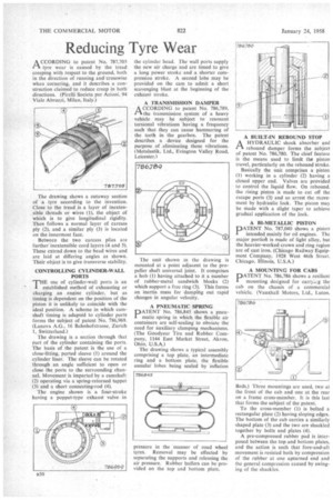
ACCORDING to patent No. 787,705 tyre wear is caused by the tread creeping with respect to the ground, both in the direction of running and crosswise when cornering, and it describes a construction claimed to reduce creep in both directions. (Pirelli Societa per Azioni. 94 Viale Abruzzi, Milan, Italy.)
The drawing shows a cutaway section of a tyre according to the invention. Close to the tread is a layer of inextensible threads or wires (1), the object of which is to give longitudinal rigidity. Then follows a normal layer of carcass ply (2), and a similar ply (3) is located on the innermost face.
Between the two carcass plies are further' inextensible cord layers (4 and 5). These extend down to the bead wires and are laid at differing angles as shown. Their object is to give transverse stability.
CONTROLLING CYLINDER-WALL PORTS
THE use of cylinder-wall ports is an established method of exhausting or charging an engine cylinder, but as timing is dependent on the position of the piston it is unlikely to coincide with the ideal position. A scheme in which camshaft timing is adapted to cylinder ports forms the subject of patent No. 786,969. (Lanova A.G., 16 Bahnhofstrasse, Zurich 1, Switzerland.)
The drawing is a section through that part of the cylinder containing the ports. The basis of the patent is the use of a close-fitting, ported sleeve (I) around the cylinder liner. The sleeve can be rotated through an angle sufficient to open or close the ports to the surrounding channel. Movement is imparted by a camshaft (2) operating via a spring-returned tappet (3) and a short connecting-rod (4). The engine shown is a four-stroke having a poppet-type exhaust valve in the cylinder head. The wall ports supply the new air charge and are timed to give a long power stroke and a shorter compression stroke. A second lobe may be provided on the cam to admit a short scavenging blast at the beginning of the exhaust stroke.
A TRANSMISSION DAMPER
ACCORDING to patent No. 786,789. the transmission system of a heavy vehicle may be subject to resonant torsional vibrations having a frequency such that they can cause hammering of the teeth in the gearbox. The patent describes a device designed for the purpose of eliminating these vibrations. (Metalastik, Ltd., Evington Valley Road. Leicester.)
The unit shown in the drawing is mounted at a point adjacent to the propeller shaft universal joint. It comprises a hub (I) having attached to it a number of rubber-metal sandwich blocks (2) which support a free ring (3). This forms an inertia mass for damping out rapid changes in angular velocity.
A PNEUMATIC SPRING DATENT No. 786,845 shows a pneu
matic spring in which the flexible air containers are self-sealing to obviate the need for auxiliary clamping mechanisms. (The Goodyear Tire and Rubber Company, 1144 East Market Street, Akron, Ohio, U.S.A.) The drawing shows a typical assembly comprising a top plate, an intermediate ring and a bottom plate. the flexible annular lobes being sealed by inflation
A BUILT-IN REBOUND STOP
AA HYDRAULIC shock absorber and rebound damper forms the subject of patent No. 786,780. The chief feature is the means used to limit the piston travel, particularly on the rebound stroke.
Basically the unit comprises a piston (1) working in a cylinder (2) having a closed upper end. Valves are provided to control the liquid flow. On rebound. the rising piston is made to cut off the escape ports (3) and so arrest the movement by hydraulic lock. The piston may be made with a slight taper to achieve gradual application of the lock.
A RI-METALLIC PISTON
PATENT No. 787,040 shows a piston intended mainly for oil engines. The major portiofl is made of light alloy, but the heavier-worked crown and ring region are of cast iron. (Chicago Railway Equipment Company, 1928 West 46th Street, Chicago. Illinois, U.S.A.)
A MOUNTING FOR CABS
pATENT No. 786,786 shows a resilient mounting designed for earryizg the cab on the chassis of a commercial vehicle. (Vauxhall Motors, Ltd., Luton,
Beds.) Three mountings are used, two at the front of the cab and one at the rear on a frame cross-member. It is this last that forms the subject of the patent.
To the cross-member (I) is bolted a rectangular plate (2) having sloping edges. The bottom of the cab carries a similarly shaped plate (3) and the two are shackled together by bolts and plates (4).
A pre-compressed rubber pad is interposed between the top and bottom plates, and the action is such that fore-and-aft movement is resisted both by compression of the rubber at one upturned end and the general compression caused by swinging of the shackles.