


Pneumatic Springing on Eagle Trailer
Page 48
If you've noticed an error in this article please click here to report it so we can fix it.
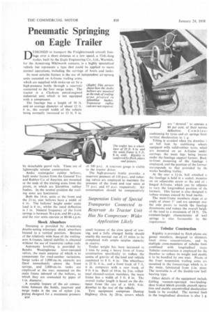
DESIGNED to transport the Freightercoach aircraft fuselage over a short distance at a low speed, a 53-ft.-long trailer, built by the Eagle Engineering Co., Ltd., Warwick, for the Armstrong Whitworth concern, is a highly specialized vehicle but represents a type that could be applied to more normal operations, • including the carriage of boats and tanks.
Its most notable feature is the use of independent air-sprung units mounted on A-frame trailing arms, which are supplied with make-up air by a high-pressure bottle through a reservoir connected to the four surge tanks. The tractor is a Clarkson petrol-engined industrial unit which is not equipped with a compressor.
The fuselage has a length of 50 ft. and an average diameter of about 12 ft. 6 in.. the overall width of the vehicle being normally increased to 13 ft. 9 in.
by detachable guard rails. These are of lightweight tubular construction.
Andre rectangular rubber bellows, built under licence from the General Tire and Rubber Co. of America. arc mounted at the ends of the trailing arms from the pivots, in which are Silentbloc rubber bushes. In the neutral position the trailing arms are horizontal.
Both the 14-in, units at the front and the 21-in, rear bellows have a width of 6 in. The bellows' height under static load is 6 in., whilst the rated deflection is 3 in. Natural frequency of the front springs is between 76 c.p.m. and 80 c.p.m., and the rear units operate at 80-84 c.p.m.
Shock Absorbers
Damping is provided by Armstrong double-acting telescopic shock absorbers located in a vertical position. Because of the relatively wide base of the trailingarm A-frames, lateral stability is obtained without the use of transverse radius rods.
Automatic levelling is provided by Ben dix Westinghouse lever-operated valves, the main purpose of which is to compensate for road-camber variations. Surge tanks of I,000-cu.-in. capacity are fitted immediately above the front springs, and 2,000-cu.-in, tanks are employed at the rear, mounted on the main frame inboard of the bellows, to which they are connected by pipes of 1-in. diameter.
. A notable feature of the air connections between the bottle, reservoir and surge tanks is the use of nylon I-in. piping designed for a maximum pressure B14 of 500 p.s.i. A reservoir gauge is visible to the tractor driver.
The high-pressure bottle provides a reservoir pressure of 110 p.s.i., and reducing valves are employed to maintain the pressure of the front and rear units at 75 p.s.i. and 65 p.s.i. respectively. Air consumption should be comparatively
small because of the slow speed of towing, and a fully charged bottle should enable the normal run of 15 miles to be completed with ample surplus capacity in reserve.
Trailer weight has been increased to 3 tons by using a heavy form of frame construction specifically to reduce the centre of gravity of the load and vehicle combined to 8 ft. 6 in. The wheelbase is 25 ft. 6 in., and a front track of 7 ft. 6 in. compares with a rear track of 9 ft. 6 in. Built of 10-in. by 3-in, rolledsteel channel-section members, the main frame has a width of 5 ft. 8 in. The overall trailer length is based on the distance from the eye of a 10-ft. 6-in. drawbar to the rear of the vehicle.
Tyre equipment comprises Dunlop Highway 10-in. by 20-in, covers which cushioning by tyres and air springs limit vertical deceleration to g.
Tilting is avoided when the drawbar i on full lock by stabilizing wheels equipped with solid-rubber tyres, whicl are mounted on an A-frame under carriage, the main legs being locate( under the fuselage support former. Back to-front mounting of the fuselage i employed, and the position of the former. corresponds to that provided by th; works handling trolley.
At the rear a 11-in. ball attached t( the fuselage is held in a socket, mountee on an adjustable screw at the end of z hinged A-frame, which can be adjustec to vary the longitudinal position of th; formers. This layout is also designed tc reduce stresses caused by load inertia.
The main-frame members slope at at angle of about 5° and are upswept owl the axle pivots to match the fuselag( dimensions and reduce the overall heigh of the load to a maximum of 18 ft. Th‘ constant-height characteristic of suck springs is also favourable to this requirement.
Tubular Construction
Rigidity is provided by flitch plates anc gusset members, designed to eliminate local stress concentrations, and by multiple cross-members of tubular forrr combined with longitudinal stays Tubular construction is employed for the drawbar to reduce its weight and enable it to be handled by one man. Pivots of the front suspension trailing arms are mounted in the forecarriage which is, in the main, fabricated from is-in. plate. The turntable is of the double-row ballbearing type.
Other details of the equipment include Girling vacuum-operated two-leadingshoe brakes Which provide smooth Operation and enable uncontrolled deceleration loads to be avoided. The normal limit in the longitudinal direction is also g.