


An Improved
Page 52
If you've noticed an error in this article please click here to report it so we can fix it.
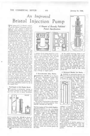
Bristol Injection Pump THE names of C. G. Nevatt, 0.B.E., and the Bristol Tramways and Carriage Co., Ltd., appear in patent No. 439,834, which describes a novel valve arrangement for incorporation in their fuel-injection pump. Dealing first with the general layout, the pump is worked by an eccentric, the sheave of which abuts on to the end of a hollow tappet, as shown in the lower portion of the accompanying drawing. The tappet would thus have a constant stroke were it not for the sliding wedge-like cam (5). This obtrudes into the path of a flange (4) on the sliding member, and prevents the full return of the tappet, so affording a control of the output.
The present invention deals with the interior valve arrangements. In this CASe the fuel arrives from the port (1) and floodS the annular chamber (6). Surrounding the plunger proper is a sleeve (2) with a conical head (7). During the downward movement of the plunger, this sleeve descends also for a short distance until the conical head bottoms. This action opens the supply to the pump space, and draws in fuel.
On the ascent, the outer sleeve (2) rises in unison with the plunger until the conical head seats into the vertical delivery conduit, after which the injection period commences. The essence of the patent is the provision' of spring rings (3) which create the friction necessary to make the sleeve partake of the initial plunger movement. An interesting feature is the entire absence of vacuum in the working space ; this should be of considerable advantage in preventing -difficulties caused by air in the supply lines,
and in patent No. 439,498 is shown a design which is claimed to meet the requirements. The inventors are H. Jacoby, of Wetzikon, and H. Ntissli, of Hinwil, both in Kanton Zurich, Switzerland. The aim of the scheme is to control the fuel flow in accordance with the amount of air ; this is achieved by B42
a number, of jets being placed in a vertical row, to which the fuel is fed by pipe 2. After passing the jets, the fuel reaches the main spray, via pipe 3.
In operation, the engine suction causes the fuel level to rise in the bore; this action brings more jets into effect. Thus, it is claimed, the supply of fuel automatically adapts itself to the air flow. A small orifice (1) is provided to prevent flooding the system, and to allow the fuel level to fall quickly during a change of engine speed.
A Steel-shrouded Alloy Piston.
PATENT No. 439,796, by A. Flower, M.S.A.E , Westbounie Lodge, Warwick Road, Acock's Green, Birmingham, discloses details of the
manufacture of alloy pistons. The drawing shows the form of the piston, and the aim of the inventor is to proportion the clearance (1) between the steel skirt and the alloy, so that at working temperatures it practicary disappears. The system suggested is as follows :—After casting, to roughmachine the upper portion to a diameter slightly less than that of the skirt, and then to force the piston through a circular die. This process is claimed to adjust the clearance to the desired amount.
The actual construction of the piston is covered by previous patents, Nos. 389,387, 389,649 and 400.131.
The Scavenging of Two-stroke Engines.
IMPROVEAENTS in the scavenging system of two-stroke oil engines form the subject of patent No. 439,753, by F. Hurum, 256, Avenida Republica Argentina, Barcelona, Spain. The system in general use injects the new air at the cylinder-head end, and exhausts via ports at the bottom of the stroke. , This inventor proposes, however, to locate both inlet and exhaust valves in the cylinder head, so as to blow the new air down one side of the cylinder, whilst the exhaust passes up the other.
In the patent drawing, which is not very informative, the inlet valve opens into a pocket (1), which is open to the injector bore (2) and the cylinder (4), no exhaust valve being shown. An interesting feature is the combustion system ; in this, the nozzle first of all injects fuel into the heated antechamber (3), the resulting spurt of flame moving up passage 2 and creating a rotational swirl in the valve pocket (4).
A Structural Member for Bodies.
ADESIGN of structural member for use in the bodywork of the heavier types of passenger and goods vehicle is shown in patent No. 429,713, by
• Park RoyalCoachworks, Ltd., Abbey Road, London, N.-W.10, and A. C.
Needs, Glaisdale, Simple Marsh Road, Addlestone, Surrey. The object is -to make a pillar which will be strong, convenient kir the attachment of adjacent members, and devoid of interior spaces.
The drawing shows the shape of the pro.posed member, which may be produced by welding a T-section on to a channel, by sheet-metal bending, or by the extruding process. In use, the space between ribs 3 is filled by battena for the attachment of the outside panelling, whilst extensions 2 are for the attachment of waist rails, or similar members. The remaining rib 1 may be used to carry gusset plates or crossmembers for the support of the roof, or an upper deck.
The absence of interior spaces is a great virtue, preventing, as it does, the condensation of moisture with its resultant corrosion at inaccessible points.