


A NEW CARBURETTER.
Page 30
If you've noticed an error in this article please click here to report it so we can fix it.
A Résumé of Recently Published Patents.
The inventor of the carburetter which Is desCribed in patent specification No. 156,097, declares that his object is to produce a component of the type which provides a mixture of constant strength at all engine speeds. He maintains that, to obtain perfect carburation, it is necessary to obtain a mixture of fuel and air which is not merely constant as regards the proportions of its various constituents, but which is also homogeneous. Experiments, he states, show that in an elementary carburetter the feed of air is proportional to the speed of the motor and that the feed of the fuel increases more quickly than the feed of air. In practice the air responds instantly to the suction at the commencement at each suction stroke, and ceases to respond immediately at the end of each suction stroke, whereas at slow speeds of the motor, the fuel responds with drag at each suction stroke, and this by reason of its inertia. For the same reason, in proportion as the speed of the motor increases, the fuel commences to flow in a continuous fashion as its inertia gives it an increasing acquired speed, thus giving too rich
a mixture. ,
The inventor sets himself the problem of giving to the air an apparent inertia winch shall be the equivalent of the inertia which is possessed by the fuel, and he does so by the employment of a small fan or air-driven turbine, which is disposed within the air inlet pipe to the carburetter. He states : "It is evident that the wheel does not increase the actual inertia of the air, but provides an apparent inertia, since it gives it an acquired speed."
Most of our readers are acquainted with the use of a wheel, propeller, air turbine, or device of that kind, placed in
carburetter, with the abject of improving the atomization of the fuel, and of ensuring the thorough mixture of the fuel and air. It is perhaps necessary to point out that the present suggestion has nothing in common with those, since the propeller is actually placed in the air inlet to the carlauretter and not in the induction pipe or in the passage between the carburetter and induction pipe. In actual fact, it is claimed for the particular type of vane wheel which is used in connection with this invention that, the air, in passing, merely rotates the-'wheel and passes from thei inlet to the. outlet of the casing in which the wheel is located, without, being stirred or agitated
Care has to be exercised, in designing the wheel, that its weight bears a proper relation to the condition under which it is expected to work. If, for example, the fan wheel were to be made too light, there would he excess of air at low speeds, and excess of fuel at high speeds; the same conditions would hold, in fact, to a, modified degree, as if there were no fan there at all. On the other hand, if the wheel were to be made toe heavy, the reverse conditions would obtain, When the throttle valve is closed, the wheel is slowed down by the pressure of the gas accumulating in front of it. This pressure also makes itself felt at the jet of the carburetter, and has the effect of driving back any fuel which might otherwise escape.
A34
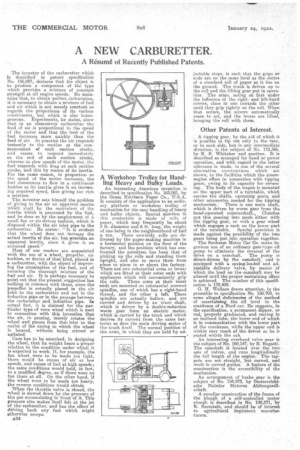
A Workshop Trolley for Handling Heavy and Bulky Loads.
An interesting American invention is described in specification No, 163,931, by the Great Northern Paper Co., U.S.A. It consists of the application to an ordinary platform or workshop trolley of mechanism for the easy handling of heavy and bulky objects. Special mention in this connection is made of rolls of paper, which may frequently be about 3 ft. diameter and 6 ft. long, the weight of one being in the neighbourhood of half a ton. . These unwieldy rolls are delivered by the paper-making machine in a horizontal position on the floor of the factory, and the problem which has confronted the patentees has been that of picking up the rolls and standing them upright, and also to move them from place to place in or about the factory. There are two substantial arms or levers which are fitted at their order ends with appliances which will conveniently grip the rolls. These arms at their inner ends are mounted on substantial screwed spindles, one of which has a right-hand thread, and the other a left. These spindles are actually hollow, and are carried and driven by an inner shaft, which is driven by a double-reduction worm gear from an electric motet., which is carried by the truck and which derives its current from the same batteries as does the main driving motor of the truck itself. The normal position of the arms, in which they are held by ad justable stops, is such that the grips or ends are on the same level as the centre of a standard roll of paper as it lies on the ground. The truck is driven up to the roll and the lifting gear put in operation. The arms, acting at first under the influence of the rightand left-hand screws, close in one towards the other until they grip tightly on the roll. When that occurs, the screws automatically cease to act, and the levers are lifted, bringing the roll with them.
Other Patents of Interest.
A tipping gear, by the aid of which it is possible to tip not only to the rear, or• to each side, but in any intermediate direction, is the subject of No. 172,366, by P. B. Whitaker and another. It is described as arranged for hand or power operation, and with regard to the latter reference is made, in None of the several alternative constructions which are shown, to the facilities which the steamengine offers in connection with tipping gears, owing to its capacity for reversing. The body of thu wagon is mounted on the upper part of a turntable, which carries the shafts, operating gears, and other accessories needed for the tipping mechanism. There, is one main shaft, which is driven by worm gear from the hand-operated countershaft.. Clutches put this gearing into mesh either with the tipping gear, or with a gear wheel which engages a rack on the lower part of the turntable. Special provision is made against the possibility of the two gears being put into operation together.
The Sunbeam Motor Car Co. make ingenious use of an ordinary gear-type oil pump to eliminate the reversal of the drive on a camshaft. The pump is direct-driven by the camshaft-, and is equipped with a spring-loaded and adjustable delivery valve, by means of which the load on the-camshaft may be altered until the proper restraining effect is achieved. The number of this specifi
cation is 172,409. • G. H. Wallace draws attention, in the preamble to specification No. 150,702, to some alleged deficiencies of the method of ascertaining the oil level in the crankcase of a Ford car. He suggests, in the specification, a permanent dipper, or rod, properly graduated, and resting in an inclined tube, the lower end of which is in communication with the lower part of the crankcase, while .the upper end is within easy reach of the driver as he is seated within the cab.
An interesting overhead valve gear is the subject of No, 160,147, by E. Bugatti. The camshaft is located over the twosets of valves, and runs longitudinally the full length of the engine. The tappets are not straight, but curved, and work in curved guides. A feature of the construction is the accessibility of the mechanism.
An arrangement of brake gear is the subject of No, 154,972, by Oesterreichisehe Daimler Motoren AkitengesellBehan.
A peculiar construction of the frame of the plough of a self-controlled •motor plough is described in No. 148,571, by R. Bernstein, and should be of interest to agricultural implement. manufacturers,