


A Half-track Attachment for Tractors
Page 54
If you've noticed an error in this article please click here to report it so we can fix it.
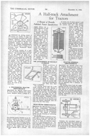
A LTHOUGH the driving wheels of ti tractors are usually of large size, they nevertheless sometimes fail to give sufficient adhesion, and to improve matters in this respect is the aim of an attachment shown in patent No. 605,814, by Nuffield Mechanizations, Ltd., H. Merrett, and C. Culpin, all of Common Lane, Washwood Heath, Birmingham, 8. •
The invention consists of a halftrack unit, readily adaptable to existing vehicles. The drawing shows an outline of the fitment in place on a standard tractor. A pair of free bogie wheels (I) is journalled on a beam (2) which is pivoted about point 3 on the axle casing. An essential feature of the scheme is that the height of the pivot pin bisects the angle between the rear-axle axis and the ground, taking one of the wheels as a centre. This means that the pressure distribution between each track and the ground is not varied by the magnitude of the pull, and that the tracks will not tend to tilt under load. The rear axle carries a sprocket (4) which drives the track in the usual way.
A TWO-WHEELED TRACTOR FROM BELGIUM
PATENT No. 606,514, which comes from Charrues _Mdlotte S.A., GemMous, Belgium, shows a design for a
two-wheeled tractor intended as an allpurpose machine for use in small-scale farming. The patent refers to a detail connected with the swivelling drawbar. The drawing shows an outline of the machine, which is powered by a 10 h.p. petrol or oil engine, and has two forward speeds and a reverse. The A36
A Resume' of Recently Published Patent Specifications
engine drives, via a built-in gearbox (1) and chain (2), a wormdriven axle fitted with a normal differential. No clutch is mentioned, but presumably one is fitted. The essence of the patent is the means for attachment of the drawbar (3); this is fixed to a ring (4) constrained onto a round boss by an angle-iron ring (5). By this means, it is possible to rotate the drawbar through any desired angle. It is difficult to see the practicability of this arrangement as the turning movement islimited by the tractor wheels.
THE ATTACHMENT OF BUS-SEAT CUSHIONS
THE problem of fixing bus seat cushions to their frames is dealt with in patent No. 605,400, by R. Bamford and I.W.H.T., Ltd., Mearclough Works,. Sowerby Bridge, Yorks. An improved method of fixing is shown, in which the usually difficult task of locating the seat bolts over their holes is simplified.
The drawing shows part of a seat frame constructed of tube, having a pair_ of cushion-supporting rails (1) of box section, the upper side being provided with an open slot. In the middle of each rail is a hole (2) for the reception of a bolt fixed to the underside of the cushion. Assembly is quick and easy; all that has to be done is to enter the seat bolts in the channels and slide the cushion rearwards until the bolts drop into their holes.
FRAM FILTER IMPROVEMENTS
PATENT No. 604,110 comes from the Fram Corporation, Providence, Rhode Island, U.S.A., and discloses the latest suggestions for the construction of filters. The scheme is intended mainly for the cleansing of lubricating oil or oil fuel.
The drawing shows a general arrangement and a scrap view showing the actual filtering surfaces. The unit consists of a stack of alternate spacer washers (1) and filtering discs (2). The latter are made of blotting-paper card, about 0.020 in. thick, whilst the spacers may also be made of the same material, but not necessarily so. • In action, the oil enters spaces 3, and by soaking through the disc, reaches the central tube (4). The foreign matter collects on the c04.110 surface of the larger discs, as shown at 5, arid as this gradually becomes filled, the liquid enters on a gradually increasing diameter, so that the resistance to flow is not appreciably increased. The patent also shows other arrangements employing different shapes of filter disc, but the basic principle is the same.
The general assembly drawing shows the filter pack held in position by a sealing cap and securing bolt. Removal of this bolt permits of the removal of the pack for cleaning or replacement.
TRACTOR STEERING ARRANGEMENTS
PATENT No. 605,920 comes from Nuffield Mechanizations, Ltd., H. Merrett and C. Culpin, all of Common Lane, Washwood Heath, Birmingham, 8, and deals with steering arrangements for tractors. The patent refers to tractors having alternative frontwheel systems—one wheel or two on an axle. With an interchangeable system like this, it is necessary to provide adaptable steering to deal with either type, and the patent shows how this can be achieved with a minimum of complication.
The drawing shows both the singlewheeled and the tNo-wheeled assembly. The whole of the front axle is detachable, and all its steering arrangements are built on it, so that by detaching the drag link (1) from arm 2 the entire steering mechanism can be removed with the axle.
Similarly, the one-wheel system is provided witb an arm (3) to receive the end of the drag link. The patent also gives illustrations showing the methods of attachment of the alternative wheel arrangements.