


An Automatically Tracking Six-wheeler
Page 64
If you've noticed an error in this article please click here to report it so we can fix it.
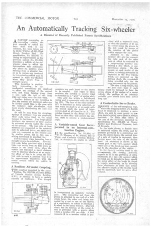
A Resume of Recently Published Patent Specifications A PATENT concerning an intereZug vehicle, the first exampt of which has been dealt with in our columns, has been taken out by Holly Whitby, of 380, High Street, Ponders End. His specification, No. 321,767, relating to improvements on his previous patent, No. 281,908, describes a vehicle of the six. wheeler class in which the intermediate axle automatically alters its position when steering from a straight line, -so as to reduce any tendency to tyre grinding which may be present in rigid six-wheelers when they divert from a straight course.
This invention is particularly interesting, as no mechanical connections are employed . to effect the trailing of the central axle, and when turning away from a side walk the tail of the body does not swing over the side walk.
Another feature of the invention is that the central and rearmost axles can be farther apart than is the case with the ordinary rigid six-wheeler, thus more evenly distributing the load over the road.
As will be seen from the drawings, springs of ordinary type are employed, their ends being fixed in the usual manner to the frame. Two longitudinal members are mounted at their centres to universal swivels under the centres of the springs. The rear ends of these members are connected to the rearmost axle by spherical joints, and their front ends are connected to the central axle by similar joints, but in this case a sliding movement is provided for.
The movement when departing from a straight course is as follows. The central axle, being provided with a torque tube, can swing from its ball joint, as shown in the lower view, when the vehicle has travelled a short distance with its steering wheels set at an angle; the effect of this is to bring the central axle to such a position that it is in approximate alignment with the centre around which the vehicle is turning..
A Resilient All-metal Coupling.
THE coupling described in the speci fication, No. 321,789, of James Bibby, of Victoria Station House, London, S.W.1, is claimed to have a certain amount of resiliency. Two flanged members are each keyed to the shafts to be coupled. The edges of these members arc notched to receive what is described as a " grid " of spring steel.
This grid lies within a bell-shaped casing and is concentric with the member (B). The face of the other member (C) is described as being spherical, so that when its shaft is at an angle with the second shaft the point of intersection shall at all times be at A. The notches formed in the flange of C are flared so that they will permit the carflan shaft to assume a predetermined angle.
A Variable-speed Gear Incorporated in an Internal-combustion Engine.
IN the specification. No. 321,684, of W. F. Thomas, of St. Helens, Isle of Wight, and Coventry Gearless Motors, Ltd., is described an engine in which
is incorporated an infinitely variable gear. The connecting rod from the piston is attached to one 'end of a bellcrank lever, the other end being connected by a rod to one of the throws of a crankshaft, to which is attached a flywheel in the usual manner. .The bell crank has its fulcrum at the point A; and is provided with a groove along which a member (B) can slide. A link connects B to a member which is pro vided with a segmental rack, so that the position of B can be varied along th9 groove in the bell crank by means of the rotation of the pinion which engages the rack.
Attached to the sliding member (B) are two connecting rods, each of the other ends of which is connected to a reciprocating member containing a free wheel, or uni directional clutch. By this means, at each stroke of the piston, a rocking movement is imparted to the free wheels, which are mounted on the driving shaft, the crankshaft being provided only for the even movements of the pistons.
The idea is very simple, but we ,feel sure that if such means could be induced to bear the severe stress of the engine of a motor vehicle, the problem of an infinitely variable gear would have been solved long ago.
A Controllable Servo Brake..
BRAKES of the self-energizing type, where the dragging action of a flexible band is employed to produce a servo effect, are said by some people to prduce more braking power than is always
desirable. To limit „ this 'effect is the aim of the invention described in specification No. 301,485 of Nestor Baillot and Ferdinand Fremaux, both of Brussels.
In the brake shown, a flexible band is employed within the drum, and by pressure produced by a connecting rod from the crank shown, the central joint of a pair of toggles is depressed, thus forcing apart the ends of the flexible band. An abutment is shown at the lowest part of the view, against which either end of the band can bear, according to the direction of the vehicle.
So far there is nothing novel in the arranement ; the novelty, however, appears to lie in .the provision of extra abutments (A) and (B) • against which the band can be brought to bear, should the servo effect of the brake be found to require moderating, as by allowing theseabutments to come into action the effective length of the flexible hand can be shortened, and its servo effect reduced.