


An American Torque Converter
Page 58
If you've noticed an error in this article please click here to report it so we can fix it.
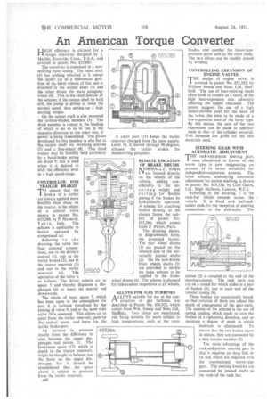
HIGH efficiency is claimed for a torque converter designed by J. Marble, Riverside, Conn., U.S.A., and covered in patent No. 655,085.
The converter is contained in a nonrotating outer casing. The input shaft (1) has nothing attached to it except the spider (2) of a differential gear. One of the bevel wheels of this unit is attached • to the output shaft (3) and the other drives the main pumpingwheel (4). This is the chief feature of the kheme; if the output shaft be held still, the pump is driven at twice the normal speed, thus setting up a high starting torque.
On the output shaft is also mounted the turbine-bladed member (5). The third member is runner 6, the blading of which is set so as to run in the opposite direction to the other two, if
power is being transmitted. The power developed by this member is also fed to the output shaft via reversing pinions (7) and a free-wheel (8). This third runner may be forcibly held stationary by a band-brake acting on drum 9; this is used when it is desired to shift the efficiency peak to a high speed-range.
CONTROLLER FOR TRAILER BRAKES
TO ensure that the brakes of a trailer are always applied more forcibly than those on the tractor, is the object of a control valve shown in patent No. 655,200, by P. Massardi,
Turi n, Italy. The scheme is applicable to brakes operated by compressed air.
Referring to the drawing, the valve has four external connec'bons, one to the driver's control (1), one to the trailer brakes (2), one to the tractor reservoir (3) and one to the trailer reservoir (4). The operation of the valve is as follows; The driver admits air to space 5 and thereby displaces a diaphragm (6) to move, the central rod downwards. • • The whole of inner space 7, which has been open to the atmosphere via port 8, is isolated therefrom by the closing of valve 9, and at the same time valve 10 is unseated. This allows air to enter from the trailer reservoir, pass up thecentral space, and leave via the trailer brake-port.
An increase in pressure results from the difference in area between the upper dia phragm and piston 11. The lowermost space (12), which is
piped to the tractor reservoir, might be thought to balance out the force on the . upper diaphragm, but it should . be remembered that the spaceabove is subject to pressure from the trailer reservoii-,
A40 A small port (13) keeps the trailer reservoir charged from the main supply. Lever 14, if moved through 90 degrees, releases the trailer brakes for manceuvring purposes.
REMOTE LOCATION OF BRAKE DRUMS MOR:MALLY, brakes
'41 are located directly on the wheels of the vehicle, adding considerably to the unsprung weight and calling for flexible piping if the brakes be hydraulically operated. A scheme for attaching brakes directly to the chassis forms the subject "of patent No. 655,366; which comes from P. Perrot, Paris.
The drawing shows, in diagrammatic" form, the proposed . layout. ••The •rear wheel drums (1) are placed on the inboard side of the universally," jointed shafts (2). On the non-driven front wheels shafts (3) are Provided . to enable the same scheme to be applied to the frontwheel drums (4). The scheme is planned for independent suspension at all wheels.
ALLOYS FOR GAS TURBINES A LLOYS suitable for use in the con
struction of gas turbines, are described in Patent No. 654,922, which comes from Win. Jessop and Sons Ltd., Sheffield. Two alloys are mentioned, one being suitable for parts subject to high temperatures, such as the rotor
blades, and another for lower-tern-. perature parts such as the rotor .body.: The two alloys can be readily joined by welding.'
CONTROLLING EXPANSION _Of
ENGINE VALVES . T , .THEHE design of engine valves is in patent No. 655,242, by William Jessop and Sons, Ltd., Sheffield. The use of heat-resisting steels often leads to trouble as a result of the high heat-expansion rate adversely affecting the tappet clearance. The patent suggests the use of a high nickel-chrome steel for the head of the valve, the stem to be made of a low-expansion steel of the Invar type. By this means, the sum of the two expansions can be made to approximate to that of the cylinder material. Full formulm are given for the two materials used.
STEERING GEAR WITH AUTOMATIC ADJUSTMENT
THE rack-and-pinion steering gear, once abandoned in favour of the worm type is now -reappearing on account of its better suitability for independent-suspension systems. The latest scheme, embodying automatic adjustment for pinion meshing, is shown in patent No. 655,130, by Cam Gears, Ltd., High Holborn, London, W.C.1.
Referring to the drawing, 1 is the rack-bar which extends across the vehicle. It is fitted with ball-andsocket ends for the reception of steering connections to the stub-axles. The pinion (2) is coupled to the end of the steering-column. The rack teeth are cut on a round bar which slides in a pair of bushes (3), one at each end of the tubular casing (4).
These bushes are eccentrically bored, so that rotation of them can adjust the depth of engagement of the gear-teeth. The essence of the scheme is the use of spring loading which tends to turn the bushes in a tightening direction, and so maintain a degree of mesh in which backlash is eliminated. To ensure that the two bushes move in unison, they are connected by a thin tubular member (5).
The main advantage of the rack-and-pinion steering gear is that it requires ,no drag link or tie rod, which are required with the conventional worm-type gear. The steering knuckles are connected by jointed shafts to the ends of the rack bar.